C
HAPTER
1
| Introduction
Description of Hardware
– 26 –
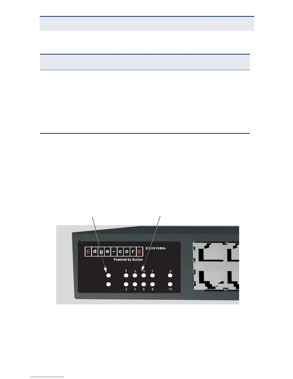
PORT AND SYSTEM STATUS LEDS
The switch includes a display panel for key system and port indications that
simplify installation and network troubleshooting. The LEDs, which are located
on the front panel for easy viewing, are shown below and described in the
following tables.
Figure 3: Port LEDs
1000BASE-LX 50/125 1300 550 m
62.5/125 1300 550 m
9/125 1300 10 km
1000BASE-LH 9/125 1310 35 km
1550 80 km
1000BASE-T 100 m
* Maximum distance may vary for different SFP vendors.
Table 1: Supported SFP Transceivers
Media Standard Cable Diameter
(microns)
Wavelength (nm)
Maximum Distance
*
 Loading...