xii
Figures
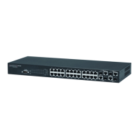
Figure 1-1 Front and Rear Panels 1-1
Figure 1-2 Stacking Ports 1-4
Figure 1-3 Port LEDs 1-5
Figure 1-4 System LEDs 1-6
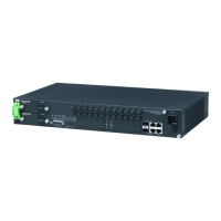
Figure 1-5 Power Supply Receptacles 1-7
Figure 2-1 Collapsed Backbone 2-2
Figure 2-2 Network Aggregation Plan 2-3
Figure 2-3 Remote Connections with Fiber Cable 2-4
Figure 2-4 Making VLAN Connections 2-5
Figure 3-1 RJ-45 Connections 3-2
Figure 3-2 Attaching the Brackets 3-3
Figure 3-3 Installing the Switch in a Rack 3-4
Figure 3-4 Attaching the Adhesive Feet 3-5
Figure 3-5 Installing an SFP Transceiver into a slot 3-6
Figure 3-6 Connecting Switches in a Ring-topology Stack 3-7
Figure 3-7 Power Receptacles 3-8
Figure 3-8 Serial Port (DB-9 DTE) Pin-Out 3-9
Figure 4-1 Making Twisted-Pair Connections 4-2
Figure 4-2 Network Wiring Connections 4-3
Figure 4-3 Making Fiber Port Connections 4-5
Figure B-1 RJ-45 Connector Pin Numbers B-1
Figure B-2 Straight-through Wiring B-2
Figure B-3 Crossover Wiring B-3