Connecting Switches in a Stack
3-7
3
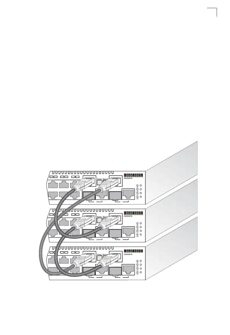
You can form a stack containing up to eight ES3526YA units or up to four ES3550YA
units. To connect switches in a stack, perform the following steps:
1. Enable the stacking ports on each unit (i.e., the Stack button pushed out)
Note: Pressing the Stack button during normal operation will cause the system to
reboot.
2. Plug one end of a stack cable (ordered separately) into the Down (left) port of
the top unit.
3. Plug the other end of the stack cable into the Up (right) port of the next unit.
4. Repeat steps 1 and 2 for each unit in the stack. Form a simple chain starting at
the Down port on the top unit and ending at the Up port on the bottom unit
(stacking up to 8 units).
5. (Optional) To form a wrap-around topology, plug one end of a stack cable into
the Down port on the bottom unit and the other end into the Up port on the top
unit.
Figure 3-6 Connecting Switches in a Ring-topology Stack
6. Select the Master unit in the stack by pressing in the Master button on only one
of the switches. Only one switch in the stack can operate as the Master, all
1
9
/2
0
2
1
/2
2
2
3
/2
4
1
92021
2
2
2
3
2
4
2
7
2
8
2
5
2
6
1
9
/2
0
2
1
/2
2
2
3
/2
4
1
92021
2
2
2
3
2
4
2
7
2
8
2
5
2
6
1
9
/2
0
2
1
/2
2
2
3
/2
4
1
92021
2
2
2
3
2
4
2
7
2
8
2
5
2
6
PWR
Diag
RPU
Stack
Master
PWR
Diag
RPU
Stack
Master
PWR
Diag
RPU
Stack
Master