Installing the Switch
3-6
3
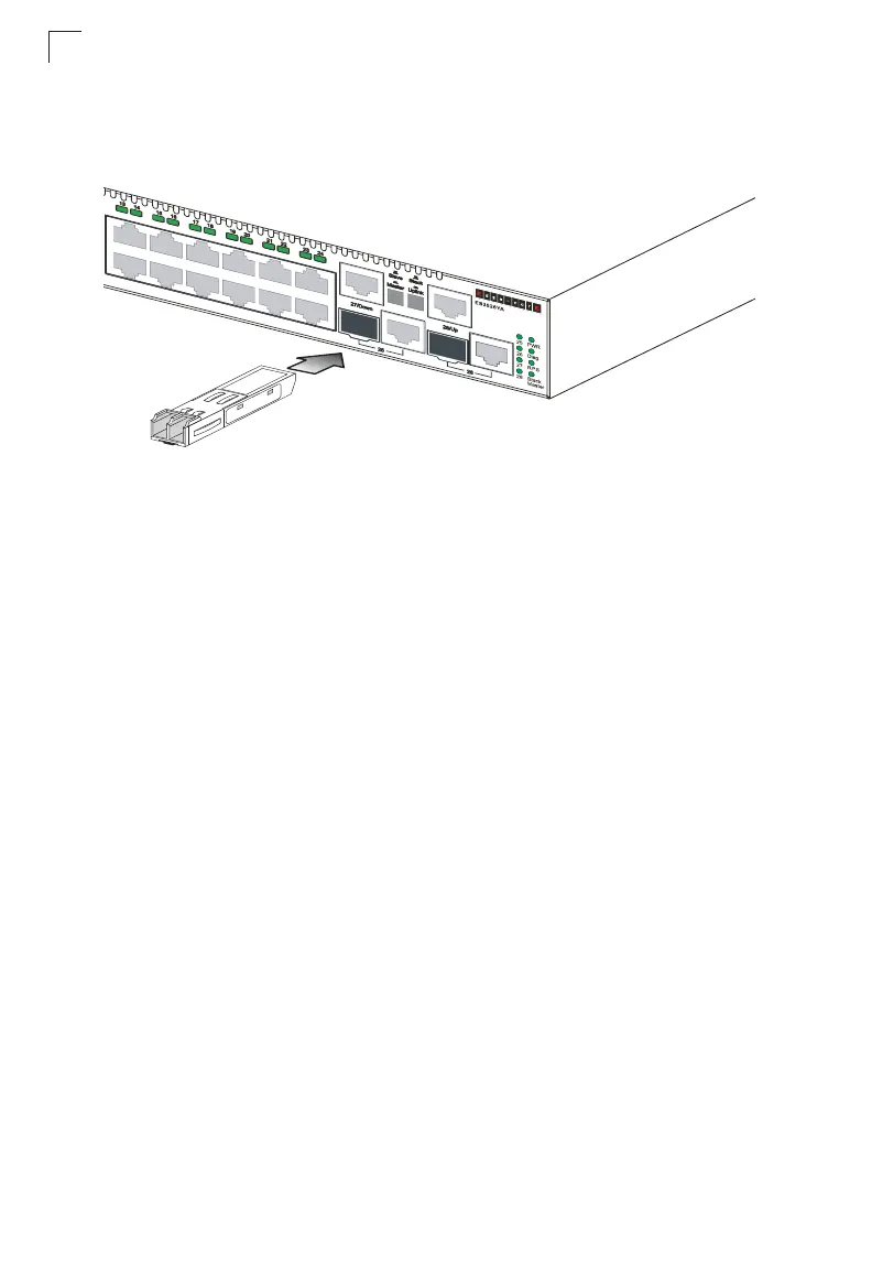
Installing an Optional SFP Transceiver
Figure 3-5 Installing an SFP Transceiver into a slot
This switch supports 1000BASE-SX, 1000BASE-LX, and 1000BASE-LH SFP
transceivers. To install an SFP transceiver, do the following:
1. Consider network and cabling requirements to select an appropriate SFP
transceiver type.
2. Insert the transceiver with the optical connector facing outward and the slot
connector facing down. Note that SFP transceivers are keyed so they can only
be installed in one orientation.
3. Slide the SFP transceiver into the slot until it clicks into place.
Note: SFP transceivers are hot-swappable. The switch does not need to be powered off
before installing or removing a transceiver. However, always first disconnect the
network cable before removing a transceiver.
Note: SFP transceivers are not provided in the switch package.
Connecting Switches in a Stack
Figure 3-6 shows how the stack cables are connected between switches in a stack.
The connection is based on Gigabit Ethernet, using Category 5 or better cables.
The
switch supports a line- and ring-topology stacking configuration, or can be used stand
alone.
In line-topology stacking there is a single stack cable connection between each
switch that carries two-way communications across the stack. In ring-topology
stacking, an extra cable is connected between the top and bottom switches forming
a “ring” or “closed-loop.” The closed-loop cable provides a redundant path for the
stack link, so if one link fails, stack communications can be maintained. Figure 3-6
illustrates a ring-topology stacking configuration.