TABLE OF CONTENTS INTRODUCTION INSTALLATION OPERATING INSTRUCTIONS APPENDIX
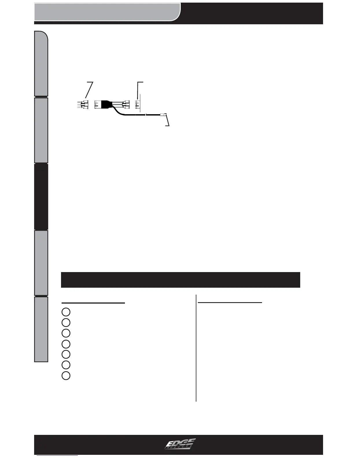
3. Connect the TPS connectors
in between the stock harness
and the sensor as shown in
Figure 13.
4. From in the cab, route the
TPS Sensor harness through
the fi re wall and into the engine
compartment.
(NOTE: Route through the
existing holes located on the
fi re wall.)
5. Locate the TPS Adapter wire
as shown in Figure 1 on page 8.
6. Plug the single wire adapter
into the end of the TPS Sensor
harness.
This concludes the Juice Har-
ness section of the installation.
Please refer to the EGT PROBE
INSTALLATION section of
this manual to continue your
installation.
FIGURE 13 - “T” Assembly
Stock
Harness
TPS
Sensor
Plugs into Main Juice harness
2003-2007 (6.0L)
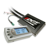
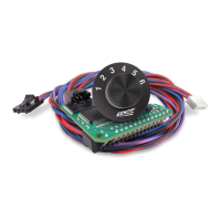
Supplied Items
Required Tools
1 Main Harness
2 Juice Module
3 Velcro Strips
4 Zip Ties
5 EGT Sensor Probe
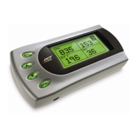
6 Juice Attitude Bridge (JAB)
7 CS/CTS Installation Guide
- Electric/Cordless Drill
- 1/8” drill bit or similar size
(for pilot hole)
- 21/64” (best size) or 5/16”
drill bit (for fi nal hole)
- 9/16” wrench or socket
- 5/8” open end wrench
- 1/8”-27 NPT Thread Tap
- Phillips screwdriver
- 5/16” or 8mm wrench
- 13mm wrench