TABLE OF CONTENTS INTRODUCTION INSTALLATION OPERATING INSTRUCTIONS APPENDIX
the tubing over the connections. (Figure 7)
6. Secure the excess cable to the existing engine wire harnesses
with supplied zip ties.
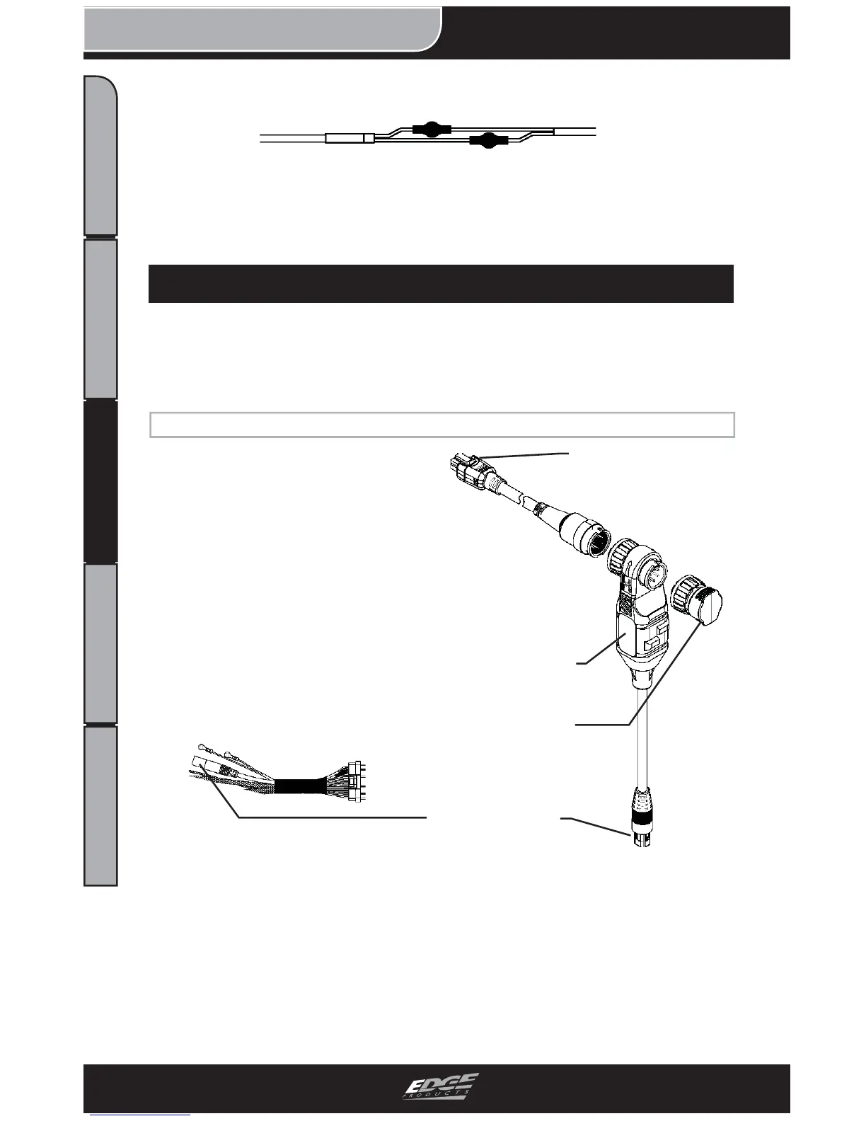
Figure 7 - Shrink Tube Final
JAB INSTALLATION
1999 to 2007 - JAB INSTALLATION
1. Locate the green connector on
the Juice Harness and plug it into
the Green connector on the JAB.
2. Under the hood, connect the 3
EAS components to one another.
A “click” will be felt and heard
indicating that the connectors are
correctly fastened.
Figure 2 - JAB System
End Cap
JAB Adapter “T”
CS/CTS Connection
Green Connectors
Figure 1 - Juice Harness
3. Route the CS/CTS Connector and cable through the fi re wall
grommet. The JAB and Juice Module will remain under the hood.
(Figure 3)
NOTE: The CS/CTS will not function unless the JAB is properly
installed and plugged into both the Juice Module and Attitude
Monitor (CS/CTS).