TABLE OF CONTENTS INTRODUCTION INSTALLATION OPERATING INSTRUCTIONS APPENDIX
MAP harness and the sensor.
Refer to Figure 6.
FIGURE 6 - “T” Assembly
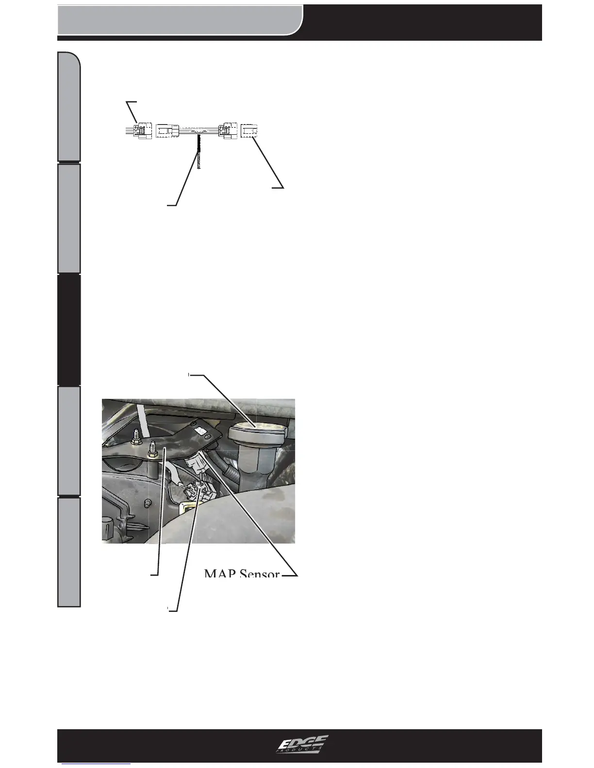
3. Figure 7 shows an assembled
MAP harness. Note that the
MAP Sensor is bolted to the
backside of the bracket shown.
Oil Cap
Bracket MAP Sensor
Edge MAP
Harness
FIGURE 7 - Final Assembly
4. Use zip ties to fasten the
harness. Keep all harness com-
ponents away from hot engine
surfaces, as well as moving
parts.
This concludes the Juice Har-
ness section of the installation.
Please refer to the EGT PROBE
INSTALLATION section of this
manual to continue your instal-
lation.
Engine
Harness
Edge MAP
Harness
MAP Sensor