TABLE OF CONTENTS INTRODUCTION INSTALLATION OPERATING INSTRUCTIONS APPENDIX
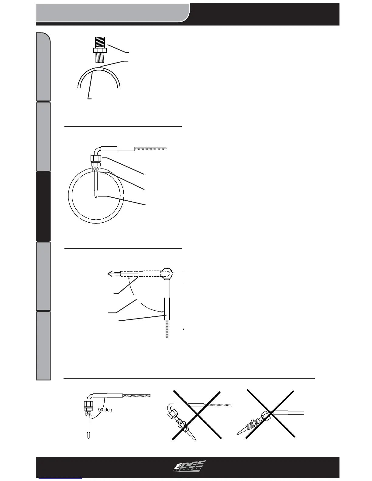
ening the tapered thread end into
the manifold. (Figure 1)
5. Tighten the fi tting so that it is
securely seated.
6. Install the probe into the fi tting,
and tighten the top nut of the fi t-
ting just tight enough to keep the
probe fi rmly mounted. (Figure 2)
NOTE: Ideally the tip of the fi t-
ting would be less than or fl ush
with the inside of the exhaust fl ow
path. (Figure 2)
7. Make sure that the probe cable
is positioned to allow best path and
minimal bending for routing to the
fi re wall.
NOTE: The probe will move ap-
proximately 90 Deg. clockwise in
the direction the nut is tightened.
Before fully tightening the nut,
make sure the cable starts 90
Degrees from the fi nal resting po-
sition. When tightened, the cable
will be correctly positioned.
CAUTION: Do not bend the
probe after installed. If needed,
loosen the probe nut, adjust the
probe, and re-tighten. Bending
the probe tubing will result in a
faulty probe.
Figure 3 - 90 Degree
Starting
Position
Tightened
Position
90 Deg.
To Fire wall
Figure 2 - Probe Insertion
Fitting
Flush
Nut
Probe
Figure 4 - DO NOT BEND
Wrong
Correct
Exhaust Manifold Wall
Figure 1 - Fitting Installation
Fitting
Tapped Hole