12
Introduction
■
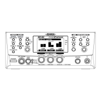
Rear Panel
fig.1-02
1 USB Connector
A USB cable can be used to connect the SD-90 to your computer. In
USB mode
, audio signals and MIDI
messages can be exchanged through this cable.
2 MIDI Connectors
These connectors can be connected to other MIDI devices, such as a sequencer, allowing the exchange of MIDI
messages (
"Controlling the SD-90 via MIDI"
(p. 77)).
IN1/IN2
: These connectors receive MIDI messages from other devices. The received MIDI messages are
sent to the computer (in USB mode) or to the internal sound generator (in MIDI mode).
OUT1/OUT2
: These connectors transmit MIDI messages to other devices.
3 DIGITAL AUDIO Jacks
These jacks can be connected to digital audio devices such as CD players and MD players to transfer digital
audio signals.
IN
: These jacks receive digital signals from other digital devices. Use a coaxial cable with
COAXIAL
, and
an optical cable with
OPTICAL
.
OUT
: These jacks send digital signals to other digital devices. Use a coaxial cable with
COAXIAL
, and an
optical cable with
OPTICAL
.
4 OUTPUT Jacks
These jacks output audio signals to your audio playback system or amplified speakers.
1
: These jacks always output the signals that are being input at the input jacks. Use the front panel
VOLUME
knob to adjust the volume.
2
: These jacks output either the signal for the rear speakers of surround reverb, or the signal from the
internal sound generator (
"Using surround output"
(p. 67)).
5 INPUT (LINE IN) Jacks
These jacks accept the input of analog audio signals from an audio device such as a CD player or MD player,
or from another MIDI device.
6 Grounding Terminal
This prevents the panel surface from developing an electrical charge.
7 AC IN Connector
Connect the supplied AC cord here. Never use any AC cord other than the one provided, since doing so may
cause malfunction.
12
34567
sd90_manual_e.book 12 ページ 2004年10月4日 月曜日 午後3時28分
 Loading...