M518-00-880 Issue A
Page 20 © Edwards Limited 2012. All rights reserved.
Edwards and the Edwards logo are trademarks of Edwards Limited.
Installation
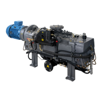
6. The flowmeter on the CXS pump (Figure 1, item 10) shows the flow rate through the CXS system only - refer to
M52800880 and adjust the water flow rate so that it meets the requirements of the T-class. Water flow to the
booster is controlled through a fixed restrictor and is designed to be the correct flow rate once the CXS has been
correctly set (for indication of booster water flow refer to the flow switch - Figure 1, item 3). Note that the
water valves will all close again after 30 seconds and the flow rate displayed by the water flow meter will
decrease - this is normal. If necessary, cycle the power to the pump to re-open the valves for a further 30
seconds to continue setting the water flow rate.
7. Inspect the water hoses, pipelines and connections and check that there are no leaks. Turn off the water supply
while you complete the remainder of the installation procedures.
Table 10 - Connections for services
3.3.5 Electrical Supply
The mains electrical supply should be brought in via the CXS Mains supply connection point - see CXS instruction
manual M52800880. Power to the EH booster motor and all ancillary instrumentation is distributed via the wiring
provided with the system.
It is possible for the three-phase electrical supply to the CXS Exd box to be phased incorrectly. The CXS Pump, driven
by inverter, will not be affected, but the EH booster will rotate in the reverse direction if the supply is phased
incorrectly. Check the direction of rotation as described below.
1. Check that the CXS/EH combination system is connected to the vacuum system or that the inlet is blanked off.
2. Check that the electrical connections and covers are tightened and closed
3. Refer to the CXS Manual M52800880 and section 4 of this manual and start the system to run the CXS pump.
Connections
Pump inlet connection
EH1200/2600 ISO 160
Pump outlet connection
CXS160/250 flange 2 inch ANSI 150 lbf/DN50 PN16 raised face
Recommended pump outlet seals PTFE envelope gaskets: ‘KLINGER’ milled type with a
1.5 mm full face insert
Air supply 1/4 inch compression fitting N
2
supply
1/4 inch compression fitting cooling-water supply
Inlet 3/8 inch BSPT male
Outlet 3/8 inch BSPT male
Check the rotation of the EH booster as described below. Backwards rotation of the booster will
result in incorrect operation invalidating the ATEX certification and may result in pump failure.
The electrical connections and Exd box cover must be fully tightened and closed before powering
up the system to perform the rotation check.
Ensure the inlet to the booster is blanked or connected to the vacuum system before you check
the direction of pump rotation. If you do not, there is a danger of objects being trapped in the
rotating rotors.
 Loading...