A546–00–880 Issue E
Page 4 © Edwards Limited 2014. All rights reserved.
Edwards and the Edwards logo are trade marks of Edwards Limited.
Introduction
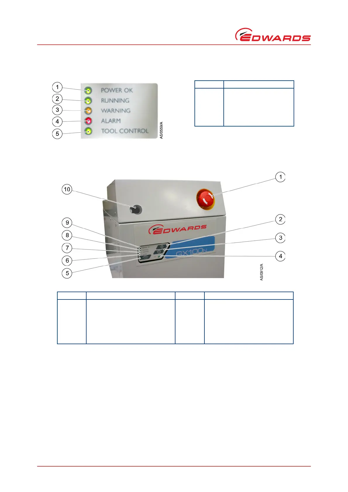
Figure 3 - The rear status panel LED indicators
Figure 4 - The front panel controls
1.4 Priority of control
The iGX system can be controlled by a number of modules: the Pump Display Terminal (PDT), from the tool through
the MicroTIM, or from the front panel local control membrane (refer to Figure 4). Only one of these can have control
of the iGX system at any one time. That is, once one of these has control of the iGX system, control requests from
the other are denied.
The PDT indicates who is in control. LEDs are also provided on the rear panel, front panel or PDT, which illuminate
to indicate 'in control'. Please refer to Figure 5.
Item Indication
1 Power OK (green)
2 Running (green)
3 Warning (Amber)
4Alarm (Red)
5 Tool control (Green)
Item Indication Item Indication
1 EMS button
*
*
Not on T variants
6 Alarm LED (red)
2 Start button 7 Warning LED (amber)
3 Stop button 8 Running LED (green)
4 AUC LED (green) 9 Power OK LED (green)
5 Local control button/LED (green) 10 Comms 5 pump display terminal
(PDT 1) connection