A546–00–880 Issue E
Page 18 © Edwards Limited 2014. All rights reserved.
Edwards and the Edwards logo are trade marks of Edwards Limited.
Installation
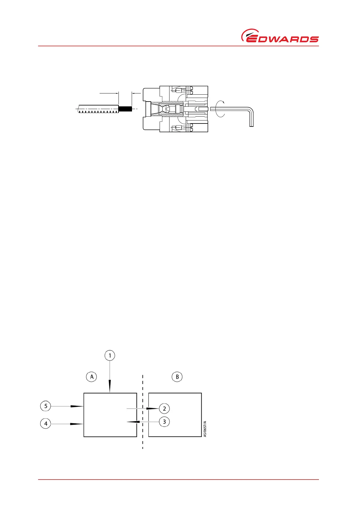
Figure 9 - Method for connecting phase wires
Systemable (T variants):
Connect the end of the supplied electrical supply cable to the electrical supply through a suitable isolator with
overload protection in accordance with local regulations - refer to the Technical Data section for pump system rating.
3.8 Connect an additional RF earth (ground) (optional)
If the iGX system will be operated in an area subject to high RF (radio frequency) emissions, in accordance with good
RF installation practice, Edwards recommends:
Using a star washer to connect the end of the earth (ground) cable (Figure 2, item 17) connected to the iGX
inlet to one of the bolts used to secure the inlet flange.
Connecting an additional earth (ground) cable to the RF earth (ground) stud (Figure 2, item 26). Use a
suitable low impedance cable (for example, use braided cable).
3.9 Connect to the emergency stop circuit
Systemable (T variants):
The pump electrical supply (Figure 2, Item 2) must be connected to an emergency stop facility. The operation of the
emergency stop function must immediately disconnect power from the pump when the emergency stop control is
operated. Returning the emergency stop control to its normal position must not result in power being re-applied to
the pump; a separate start or reset control must be used for this.
The EMO connector (Figure 2, item 10) must also be connected to an emergency stop facility to stop the pump
immediately, in the same way as the emergency stop function. Refer to Figure 10 and Table 5 for connection details.
Figure 10 - Connections to emergency stop circuit (systemable)
A. Customer Emergency stop facility
B. iGX system
1. Reset/Start
2. Electrical supply to the iGX system
(Figure 2, item 2)
3. EMO (Figure 2, item 10)
4. Emergency stop
5. Electrical supply