© Edwards Limited 2014. All rights reserved. Page 19
Edwards and the Edwards logo are trade marks of Edwards Limited.
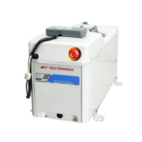
Installation
A546–00–880 Issue E
Remote (optional):
Note: If not connecting to control equipment, fit the external EMS shorting plug supplied to the EMS connector
(Figure 2, item 11) on the rear of the iGX system. If not, the iGX system will not be able to operate.
If required, connect customer supplied control equipment to the iGX system to shut it down in an emergency using
the EMS connection (Figure 2, item 11 and Table 5). The emergency stop control must be compliant with IEC 60947-
5-1 (This should be a red self latching mushroom push button on a yellow background).
3.10 Connect the cooling water hoses
Note: For optimum water cooling, ensure that the cooling water supply complies with the data given in Table 1
and are connected in parallel (refer to Figure 11). Edwards recommends that quick connectors (provided)
be used to reduce the risk of water spillage during connection/disconnection.
Connect the cooling water supply as follows:
1. Remove the dust-caps from the cooling water inlet and outlet.
2. Apply Loctite 577 (not supplied) to all male threads prior to installation.
3. Connect the reducing bushing (3) to the threaded end of the coupler (2).
4. Connect this sub-assembly to the water return port on the pumping system (4).
5. Connect the threaded end of the nipple (1) to the customer water return line.
6. Connect the reducing bushing (3) to the threaded end of the nipple (1).
7. Connect this sub-assembly to the water supply port on the pumping system (5).
8. Connect the threaded end of the coupler (2) to the customer water supply line.
9. Connect the customer supply and return hoses to the pump.
10.Turn on the cooling water supply.
11.Inspect the water hoses, pipelines and connections and check that there are no leaks.
Turn off the water supply while completing the remainder of the installation procedures.
3.11 Accessories
Refer to the individual accessories manuals for installation, information, refer to Section 7.3.
The disconnect box when fitted, is used to energize and isolate the power supply to the system. It also allows the
isolation of the electrical supply during an emergency, and for maintenance and trouble shooting the system, thereby
satisfying SEMI S2 requirements. The photohelic switch/gauge when fitted, allows monitoring for loss of extraction
from the enclosure, thereby satisfying SEMI S2 requirements.
Do not leave the cooling water supply turned on until after completing the electrical installation
of the pump. If so, condensation may form inside the enclosure and there may be a risk of electric
shock.