The pump controller provides the user interface control panel. The pump may be operated
in these modes:
• Manually, using the buons on the user in
terface panel control panel. Refer to
Figure 1 on page 11, item (1) and Figure 2 on page 12.
• Remotely via serial communicaons or digital and analogue process control
(parallel), via the 15-way D-type interface connector. Refer to Figure 1 on page 11,
item (8) and Connecon for remote control and monitoring on page 20.
• In addion, the pump can also be controlled via a digital operator which is available
as an accessory. It is connected to the pump via the digital operator connector
socket on the user interface panel Figure 2 on page 12, item (10).
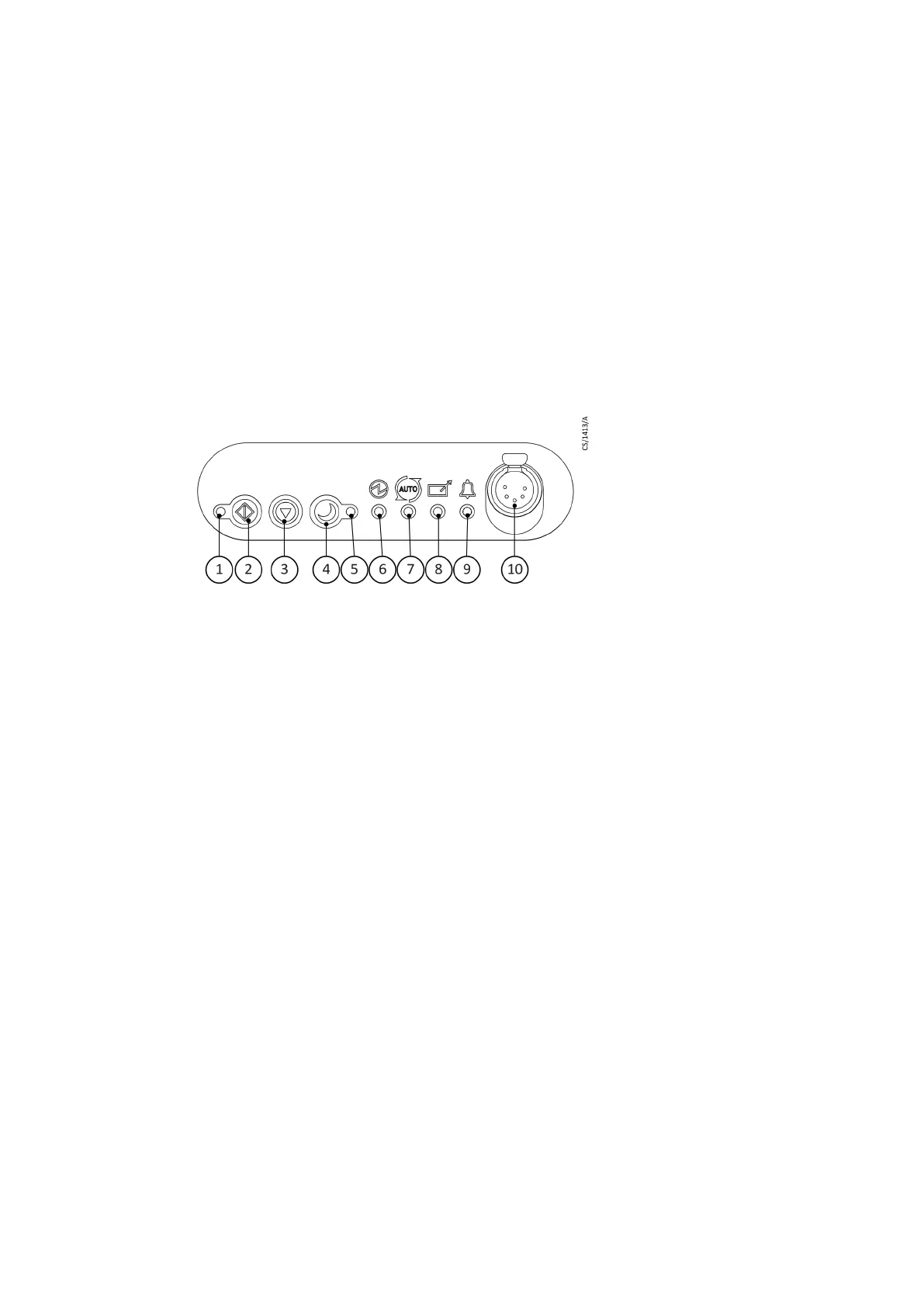
User interface control panel
Figure 2
Interface control panel
1. Run indicator LED
2.
St
art buon
3. Stop buon
4. Standby buon
5. Standby mode indicator LED
6. Power indicator LED
7. Autorun status LED
8. Remote indicator LED
9. Alarm indicator LED
10. Digital operator connecon socket
Logic interface
The logic interface has been designed to support both serial control and parallel control and
monitoring, operang through one connector.
The pump con
troller can be operated via the 15-way D-type logic interface connector Figure
1 on page 11, item (8). The signals on the logic interface are of the following types:
• Control inputs: these are switch-type and analogue signals that are used to control
the pump.
• Status outputs: these outputs idenfy the status of the system.
Autorun
The pump is provided with the opon of an autorun facility. This is selected by the switch to
the rear of the pump system Figure 1 on page 11, item (7).
Refer to Operaonal modes on page 22 for more informaon.
Auxiliary connector socket
An auxiliary control connecon is provided on the rear panel of the pump system, refer to
Figure 1 on page 11, item (6). This is to control an oponal inlet valve and be operated in
A770-10-880A - General descripon
Page 12

 Loading...


