parallel with the pump NORMAL output signal, that is, the (normally closed) valve opens
when the normal signal becomes acve (pump a
t speed) and closes when stop is selected or
there is a fault condion. Reacon me will be in line with valve selecon. The output signal
is 24 V d.c.
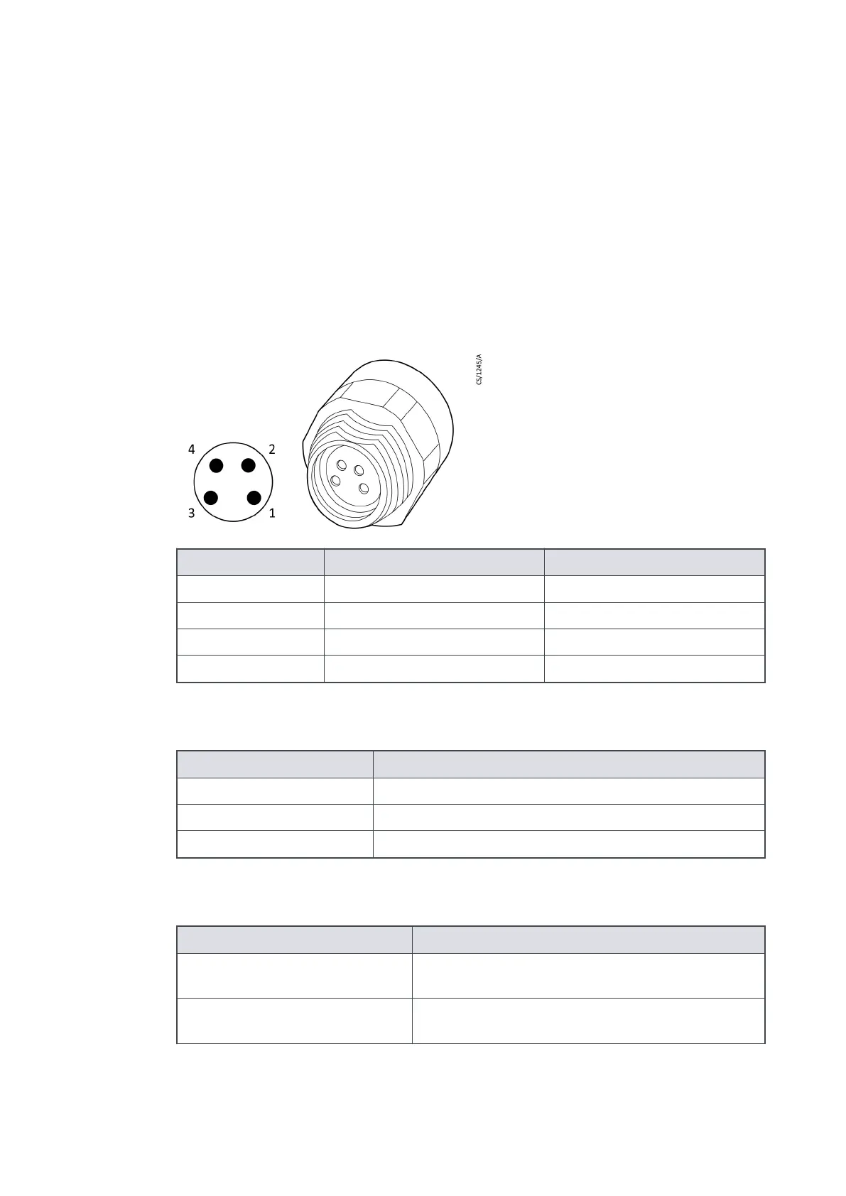
The connector is shown in Figure 3 on page 13 with the polarity of the pins marked when
the valve is energized.
The auxiliary connector is regulated to 24 V d.c. to control the accessories. If the auxiliary
load current exceeds the value in Table 1 on page 13 the output will shut down to protect
the pump controller.
Recommended mang plugs for this connecon are detailed in Table 2 on page 13.
Figure 3
Valve connector showing pin numbers
Pin number Signal Polarity
1 0 V return Negave
2 Not connected -
3 Not connected -
4 Switched +24 V Posive
Table 1
Auxiliary load currents
Descripon Data
Connector plug Phoenix part number SACC-DSI-M 8FS-4CON-M12/0.5
Voltage output 24 V d.c. -25%, +10% (18 V d.c. to 26.4 V d.c.)
Current output 500 mA
Table 2
Recommended mang plugs
Descripon Data
Mang connector plug; screw
connecon, straight
Phoenix part number SACC-M 8MS-4CON-M-SW
Mang connector plug; solder
connecon, straight
Phoenix part number SACC-M 8MS-4CON-M
A770-10-880A - General descripon
Page 13

 Loading...


