AutoCal V3 User Guide
support@efilive.com - 13 - www.efilive.com
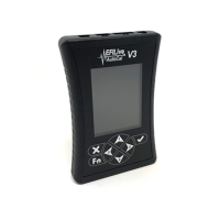
AutoCal V3 Display
The AutoCal LCD footer displays a range of communications information to assist
users.
LED Communication Indicators
5 LEDs, from left to right display the following communications information.
Green: RS232 serial data interface is active.
Orange: Data logging is active - not yet implemented. This LED will never
illuminate until this is implemented.
Blue: SD Card write in progress - - not yet implemented. This LED will
never illuminate until this is implemented.
Orange: OBDII interface is active.
Green: USB interface is active.
Active Communications Protocol
The active communications protocol is displayed on the right hand side of the
footer. The display is broken into three distinct areas using the format XXX YY ZZ
where;
1. XXX is the current protocol in use and is one of:
CAN = Controller Area Network Protocol; used by most vehicles after 2004.
VPW = Variable Pulse Width Protocol; used by GM vehicles prior to 2005.
2. YY is the type of CAN protocol in use and is one of:
LD = Light Duty (aka SAE-J1979).
HD = Heavy duty (aka (SAE-J1939).
This 2 letter code will be omitted when the protocol is VPW.
3. ZZ is the number of controllers detected.
Power-Up Modes
Hold Fn key to boot into dead-poll. Used primarily when a firmware upgrade
has not executed correctly.