Page 10 (40)
Rev 1 2018-03-21 www.elcon.se
Go to INDEX.
3.3 CONNECTIONS FOR RES ISTANCE MEASUREMENT OF A PRE-INSERTION RESISTOR.
3.3.1 SAFETY REGULATIONS.
When only one side of the breaker is connected to earth (ground), special precautions must be observed. To protect
service personnel and the measuring equipment from surges, the following important rules must be followed closely.
• The SA10A case must be grounded.
• All circuit breaker connections and disconnection’s must be made only while the breaker poles are closed and
connected to earth (ground) on least one side.
• To avoid unintentional breaker operation! Never do any work on a circuit breaker unless the control circuits of the
breaker are disconnected from the SA10A control outputs.
• The reference resistor itself and connections to the reference resistor must be well isolated.
• Warning! Do not short-circuit or touch the auxiliary voltages to and from the SA10A.
Use of touch-protected connectors is required for personal safety.
3.3.2 PRINCIPAL OF MEASURE MENT.
The auxiliary DC-voltage to the coils are used as a voltage source. The voltage division between the pre-insertion resistor
and a reference resistor is used to calculate the resistance of the pre-insertion resistor.
Selection of reference resistor.
Select the reference resistor in the same range (or lower) as the pre-insertion resistor. Use a power resistor (>= 10W).
Current will flow during a short time i.e. the pulse length set for coils.
The voltage across the reference resistor and the pre-insertion resistor are recommended to be greater than 20VDC and
must be less than 300VDC. Try to get as high current as possibly to avoid influence from surrounded capacitive current.
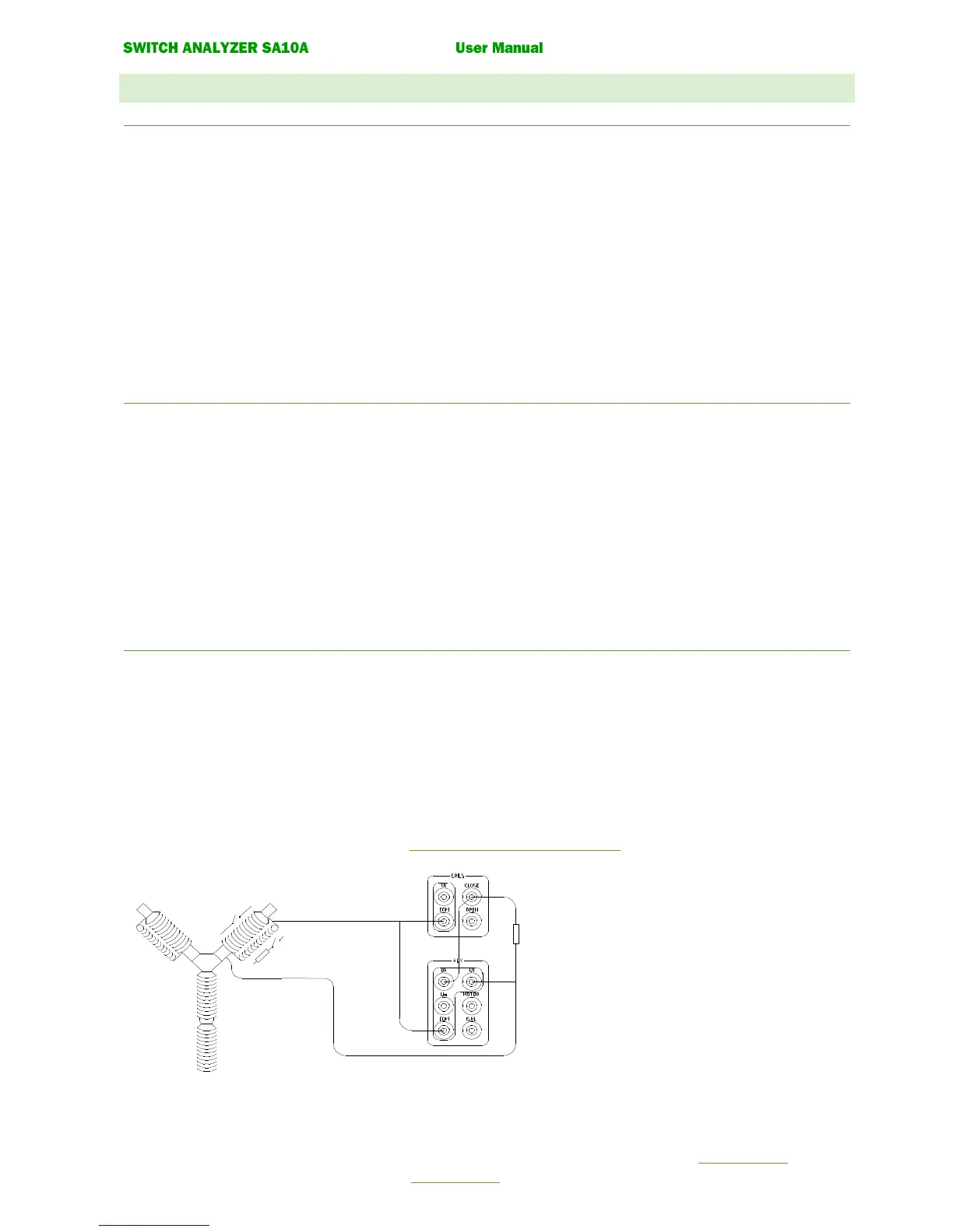
3.3.3 CONNECTION .
See figure 2.5. Make sure that the Resistor itself and connections to the reference resistor are well isolated.
Connect a wire between COILS:COM and AUX:COM
Connect a wire between output COILS:CLOSE and measuring input AUX:Uk.
Connect a reference resistor between output COILS:CLOSE and measuring input AUX:Ul.
Connect the pre-insertion resistor between AUX:Ul” and AUX:COM.
Connect the breaker coils to the SA10A for a normal CO-operation (not shown in figure 2.5).
Note! Do not connect the motor to SA10A. See 3.4.2 Connection of operating coils. for connections.