Page 27 (40)
Rev 1 2018-03-21 www.elcon.se
Go to INDEX.
7.2.5 GROUNDING.
Resistance between from power inlet ground pin to Ground spade terminal < 0.5Ω
Resistance between from power inlet ground pin to 200A + spade terminal < 0.5Ω
Resistance between power inlet ground pin to D-Sub shield RS232 < 0.5Ω
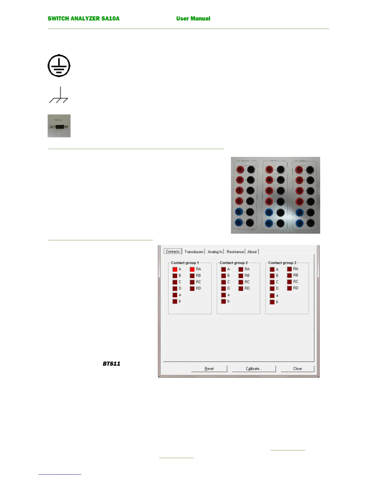
7.2.6 CHECK MAIN CONTACT INPUTS.
1A,1B,1C,1D,2A,2B,2C,2D,3A,3B,3C,3D.
Connect ampere meter + to Red banana jack on contact.
Connect ampere meter - to Black banana jack on contact.
Test current for all main contacts should be 25 - 35mA.
Indication in service menu for each contact should be seen.
7.2.7 CHECK AUXILIARY CONTACT
INPUTS. 1A, 1B, 2A, 2B, 3A, 3B.
Connect ampere meter + to Blue banana jack
on contact.
Connect ampere meter - to Black banana jack
on contact.
Test current for all auxiliary contacts should
be 8 - 12mA.
Indication in service menu for each contact
should be seen.
To open this window in .
Click function Control unit from the menu Service.
Select tab Contacts.