3.Installation of Refrigerant Lines (outdoor unit)
9.52 350~420
15.88 750~800
19.05 1000~1400
9.52 60 ~90
15.88 30 ~60
19.05 20 ~35
2.Operation on Tubing Connection
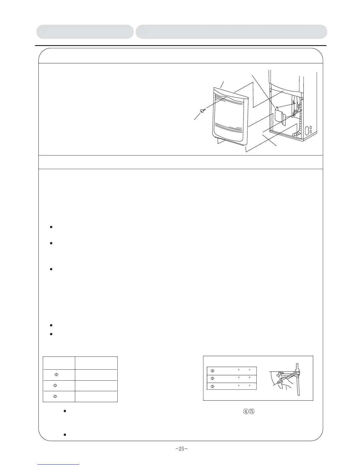
1) Remove 1 screw from handle of inlet grid, pull out to
your own direction and take inlet grid out. (As the
underside of inlet grid, is embedded in the bottom base,
please pull upward and take it out.)
2) Take down tap bolt (1) for securing pipe protection
cover, and remove pipe protection cover.
Pipe protection cover
inlet grid,
Bolt ... 1
Tap bolt 4X10 ... 1
After end of operation, it is necessary to install
according to original conditions.
Tubing procedure:
1. Keep stop valve on outdoor unit in "off" status (ex-factory specification) as original, dismantle end caps
on refrigerant lines and the unit, and proceed quickly flare connection.
If being put aside for long period after end caps being removed, breakdown may happen to tubes
because of invasion of dust, water and foreign matter into pipe, so please proceed connection operation
rapidly.
Before tightening flare nuts, a layer of attached cooling engine oil should be thinly applied on the sealed
pad surface between tubes and connectors.
Please proceed tubing connections with two wrenches and refer to the following table for tightening
torque.
2. Proceed flare-connecting operation in succession and interconnect all refrigerant lines.
After pipes being connected, leakage detector or soup water must be used to check if there are any
leaks.
3. Proceed evacuation from service entrance of stop valve on the outdoor unit.
4. After completion of above operation, keep stop valve (commonly used by liquid and gas) on the outdoor
unit totally open. By then, refrigerant cycle between indoor and outdoor unit is all connected.
Attentions on application of flexible couplings
Please apply flexible couplings at indoor lateral interconnecting areas.
Bending angle cannot exceed 90 degree, and bending cannot be repeated more than 3 times.
To reach appropriate torque as per torque wrench
When without torque wrench,
please take following method as
standard: when tightening flare
nut with wrench, stop it and only
rotate to angle stated as right
table when tightening torque
increases quickly.
External dia. of
copper pipe(mm)
Torque (kg.cm)
Standard for torque angle
Note: Please apply attached refrigerant lines thermal insulation materials for insulation on indoor
lateral flare connection areas, and please make sure to proceed the operations stated as item
3&4.
Nonoxide brazing must be applied to pipes when proceeding brazing.
INSTALLATION MANUAL 3.3/3.4Installation of Refrigerant Lines & Drain Line