4. Installation of Refrigerant Lines (indoor unit)
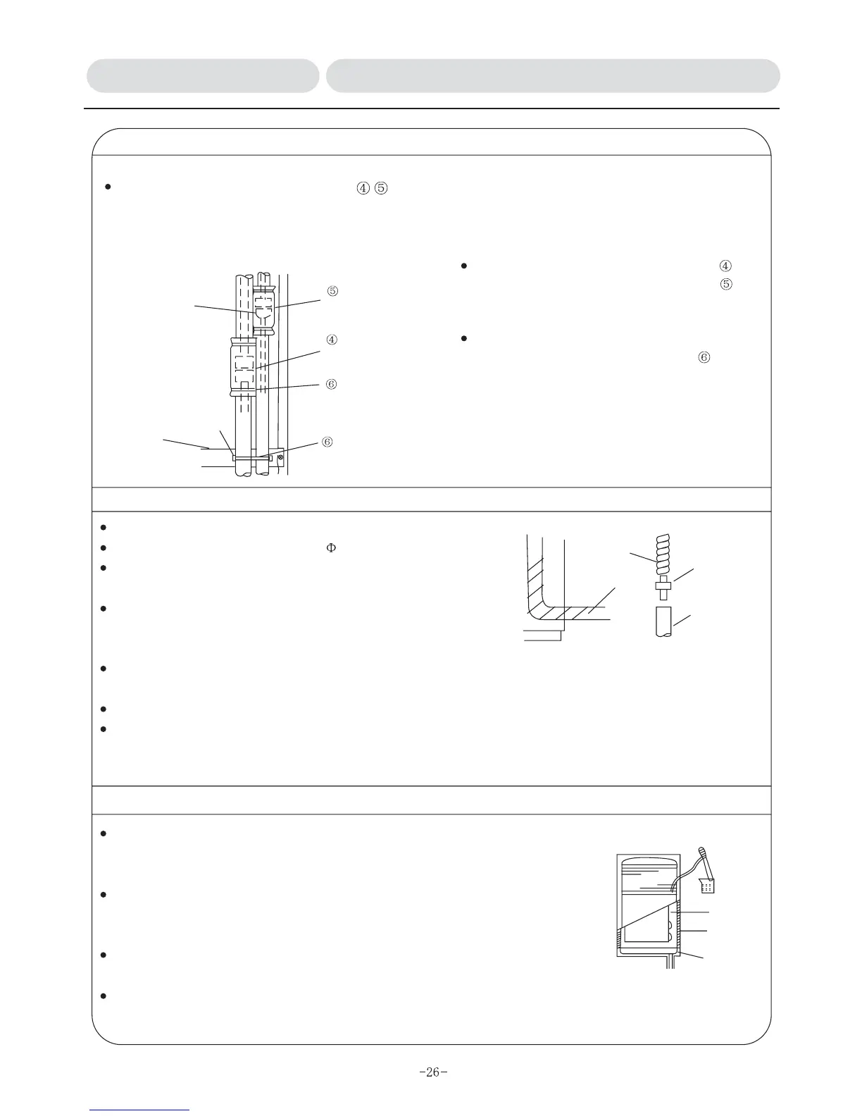
Thermal insulation on interconnecting areas
Please use reliable thermal insulation on the areas, do not let flare connection and where
refrigerant lines come out.
(Condensing frost may produce and drip down without proceeding thermal insulation on interconnecting
areas.)
Liquid Tube
thermal insulation
material for liquid
tubes
Suction Tube
thermal insulation
material for suction
tube
Tie
Frame
Angular hole
Tie
Please get the tie across the angular hole on the frame to secure lines.refrigerant
Please locate thermal insulation material for
suction tube and thermal insulation material for
liquid tube as per up and down position, which will not
produce sliding and align in one line one by one. .
After installation of thermal insulation material,
please secure refrigerant tubes with tie on the
frame below interconnecting area of tubes to prevent
moving of refrigerant tubes. Intake grille is unable to be
installed when refrigerant lines are in moving
condition
5.Installation of Drain Line
Drain line must be inclined downward (minimum 1/100).
Drain line must be PVC pipes with 26 of external diameter.
Drain hose can be matched according to spot construction to cut
with knife.
Attached drainpipe union shall be applied when interconnecting
and glued securely with PVC binding agent, making sure that
the pipe is not leaking.
Please do not put drain pipe directly to the sewer that may produce sulfur gas or a location that may
produce bad smell.
Please make sure no water leakage at interconnecting area of drain pipes.
When drain pipe has to cross indoor, thermal insulation material (foam polyethylene with gravity of
0.03kg/m and minimum 9mm of thickness) from the market must be applied to wrap the pipe and stick
adhesive tape on the surface to prevent invasion of air and condensation.
3
Drain hose
Drain pipe union
Plastic water pipe
Drain pipe
(On the spot)
6.Ensuring drainage
After completion of installing drainage line, make sure that the line is draining
water out and there is no water leakage at connecting area. ( It must be
ensured too during suction operation when installation).
Insert effusion pipe (self-configuration by installation personnel) into the
evaporator water-guide plate on the right lateral of air outlet with injection
of about 1000ml water.
Gently proceed effusion oriented to water-guide plate on the right side of heat
exchanger or internal wall of the unit.
For the conditioner with heater, please be careful not to wet the unit as there is a heater installed in front of
heat exchanger.
Water
Water-guide plate
Internal wall
Catch basin
INSTALLATION MANUAL 3.3/3.4Installation of Refrigerant Lines & Drain Line