12
Rev G
S3−
−−
−
TR400 Wiring & DIP Switches
TR400 wiring schematics, continued
During a Stop condition, any slight movement of the shaft or magnetic disc could activate the
control relay and start the motor if the Motor Auxiliary, Normally Open Contact (MS Aux n.o.) is
not wired in series. To prevent starting the motor accidentally, always use the proper
LOCKOUT TAG OUT procedures. Failure to observe this warning could result in an injury to
persons or damage to equipment.
Motor
shutdown
schematic
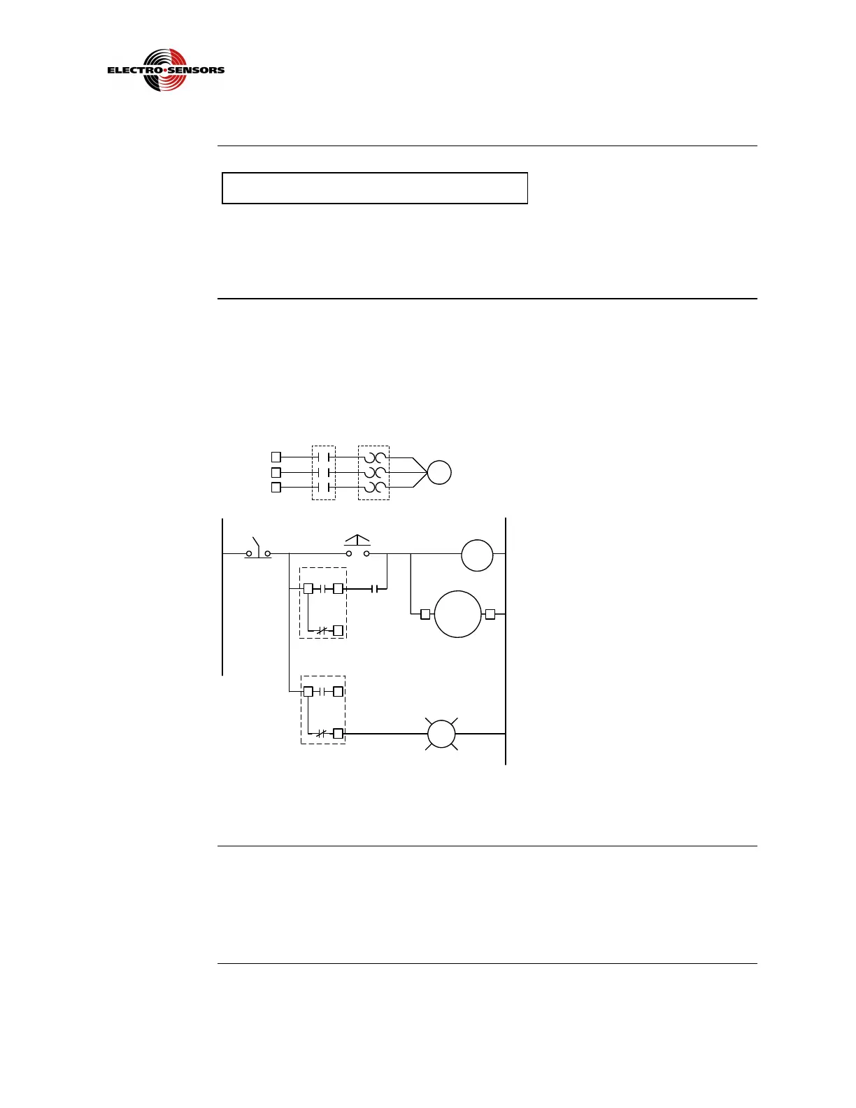
Figure 3 shows a Stop Command Wiring schematic, designed to prevent an
accidental motor startup.
Figure 3: Wiring Schematic to Disable the Alarm on a Stop Command
Input power
wiring
The TR400 standard comes set-up for 115 Vac, 6VA at 50/60 Hz. An external 1/16
amp slow-blow fuse must be provided by the customer. AC power will tie to TB1−1,
Line, and TB1−2, Neutral. Optionally it can be ordered in 230 Vac and 10-30 Vdc.
See Figure 2.
MS Motor Starter (not supplied)
OL Over Load
n.o. Normally open (relay is in a deactivated
state)
MS
TR400
Line
Neutral
Start
Momentary
Internal
On TR400
Warning Light,
Horn, Solenoid, etc.
Internal
On TR400
Stop
Maintained
MS
Aux
MS
OL
n.o.
Motor Shutdown with Alarm
 Loading...