20
Rev G
S4−
−−
−TR400 Set-
TR400 parts and functions
Overview
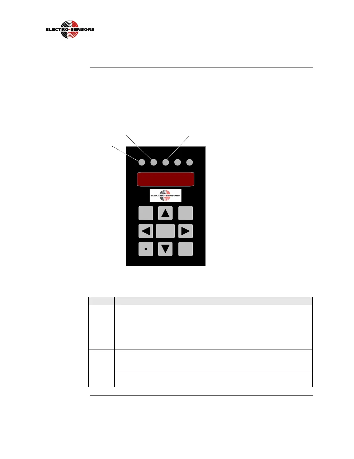
The TR400 face contains five (5) status LEDs, a four-digit display, and a keypad
containing nine (9) keys. See Figures 9a and 9b; the letters in Figures 9a and 9b
represent each part on the front panel of the TR400. The Parts and Functions table
that follows describes the function of each the parts.
Sensor DIP switches, located on the bottom of the TR400, are not discussed in this
section; see “TR400 DIP Switches” in Section 3.
Figure 9a: TR400 Front Panel Description
Table 3: TR400 Panel Parts and Functions
Part Function
A The REV LED will light when either variable 15 or 16 is being
programmed for reverse direction. By pressing the REV key when in
variable 15 or 16, the REV LED will light and stay lighted until you exit
Program Mode and will re-light every time you select and enter that
variable. It will also light when the TR400 is programmed for Quadrature
Mode, where signal B leads signal A.
B The PROG LED will light when the VAR key is pressed, indicating
Program Mode. It also turns on when the DIAG key is pressed, entering
Diagnostic Mode.
C The OUT 1 LED will light when relay “1” is activated. Relay “1” is
enabled by variable 13, and its set-point value is entered in variable 07.
Continued on next page
TR400 RATEMETER
0 0 0 0
REV PROG
OUT
1
KEY
ERR
OUT
2
REV
DIAG
VAR
ENTER
A
C
 Loading...