17
Rev G
S3−
−−
−TR400 Wiring & DIP Switches
TR400 DIP switches
Sensor DIP
switches
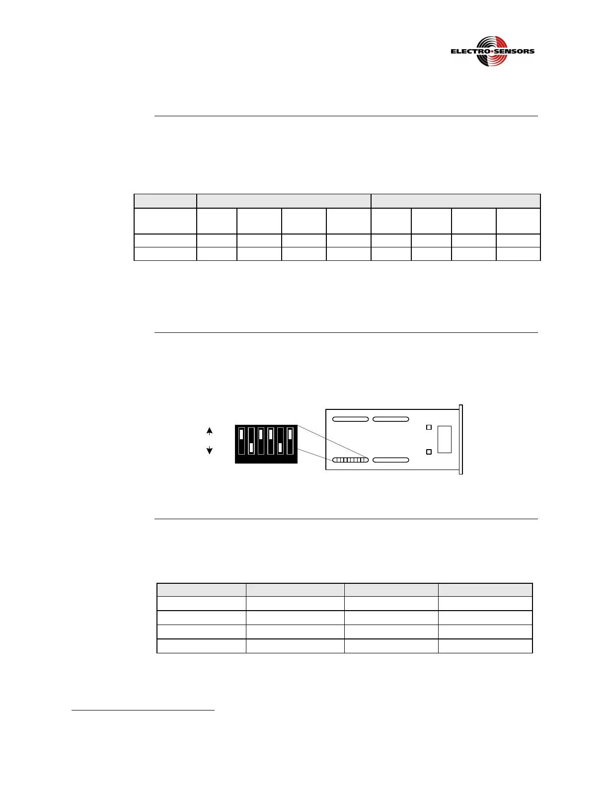
The sensor DIP switches are located on the bottom of the TR400, as shown in Figure
8. Sensor input and switch information is shown in Table 1.
Table 1: Sensor Input Configuration DIP Switches
Input
Channel A TB2−
−−
−7 Channel B TB2−
−−
−8
Input Type NPN PNP Mag. 2
Wire
Logic
Level
NPN PNP Mag. 2
Wire
Logic
Level
Switch ON 5 6 4 None 2 3 1 None
Switch OFF
4, 6 4 ,5 5, 6 4, 5, 6 1, 3 1, 2 2, 3 1, 2, 3
Note: All Electro-Sensors, Inc., digital 3 and 4 wire sensors are NPN open
collector output.
TR400
standard DIP
switch settings
Since all sensing devices produced by Electro-Sensors, Inc., are NPN open collector,
the standard switch settings are 2 and 5, set to ON, and all others set to OFF, as
shown in Figure 8.
1 2 3 4 5 6
1 2 3 4 5 6
OFF
ON
Figure 8: TR400 Sensor Switch Settings
Sensor
connections
Sensor connection information is shown in Table 2.
Table 2: Sensor Connections
Connection Sensor 906/907 ESI Prox ESI Other
TB2
5, Common
Clear/White Blue Black
TB2
6, Supply
Red Brown Red
TB2
7, Signal A
Black Black Clear/White
TB2
8, Signal B
*Green N/A
TP
PT
Green
Note: If the signal is reversed, swap signal A and signal B wires.
TP
∗
∗∗
∗
PT
Present in bi-directional version only.
 Loading...