13
Rev G
S3−
−−
−TR400 Wiring & DIP Switches
4-20 mA/0-10 Vdc analog output
4-20 mA/0-10
VDC analog
output
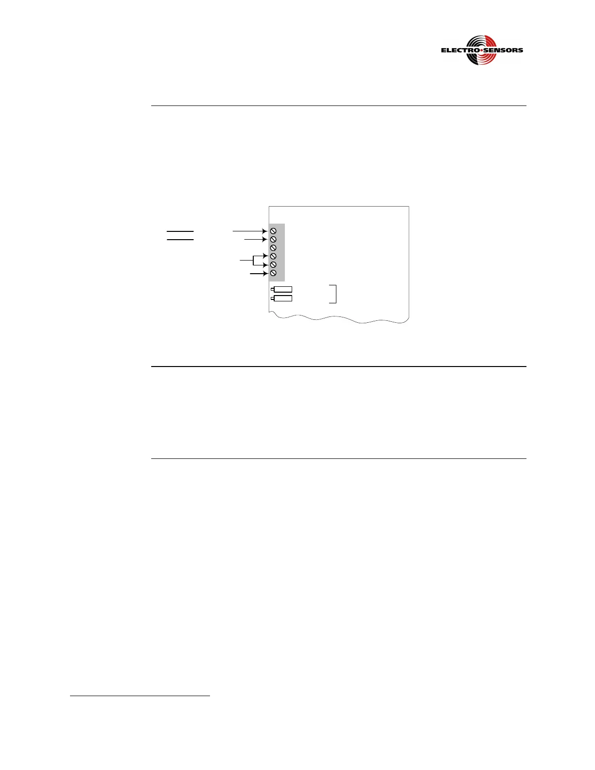
The 4-20mA output supports a maximum load resistance of 500 ohms. The analog
output plus (+) signal is at TB1−5, and the negative (-) signal is at TB1−4, as shown
in Figure 4. This applies for both 0-10VDC
1
and 4-20mA
See the Diagnostics section for additional information about the analog outputs.
1
2
3
4
5
6
TB1
(–)
(+)
Analog Output
Offset Pot
Span Pot
4-20 mA/0-10 Vdc
4–20 mA/
0–10Vdc
DC Power AC Power
(+) Line (L1)
(-) Neutral (L2)
NC
Analog Output Aux
Figure 4: Wiring for Analog Outputs 4-20 mA/*0-10 Vdc
Analog Output
Aux
Analog Output Aux is currently only used with the TR400 when the optional 6 relay
board is installed. When the 6 relay option board is installed, 4-20mA is output at
TB1-5 and 0-10Vdc is output at TB1-6. The common for both is at TB1-4. Only one
output can be calibrated at a time. Only one output should be connected and used at a
time.
1
When analog is ordered, 4-20mA is standard and 0-10VDC is optional.
 Loading...