15
Rev G
S3−
−−
−TR400 Wiring & DIP Switches
Single-channel and quadrature signal wiring
Signal types
There are two (2) signal types: Single Channel and Quadrature:
• Single Channel − Rate information is provided by a single pulse generator
connected to channel A, input terminal, TB2−7.
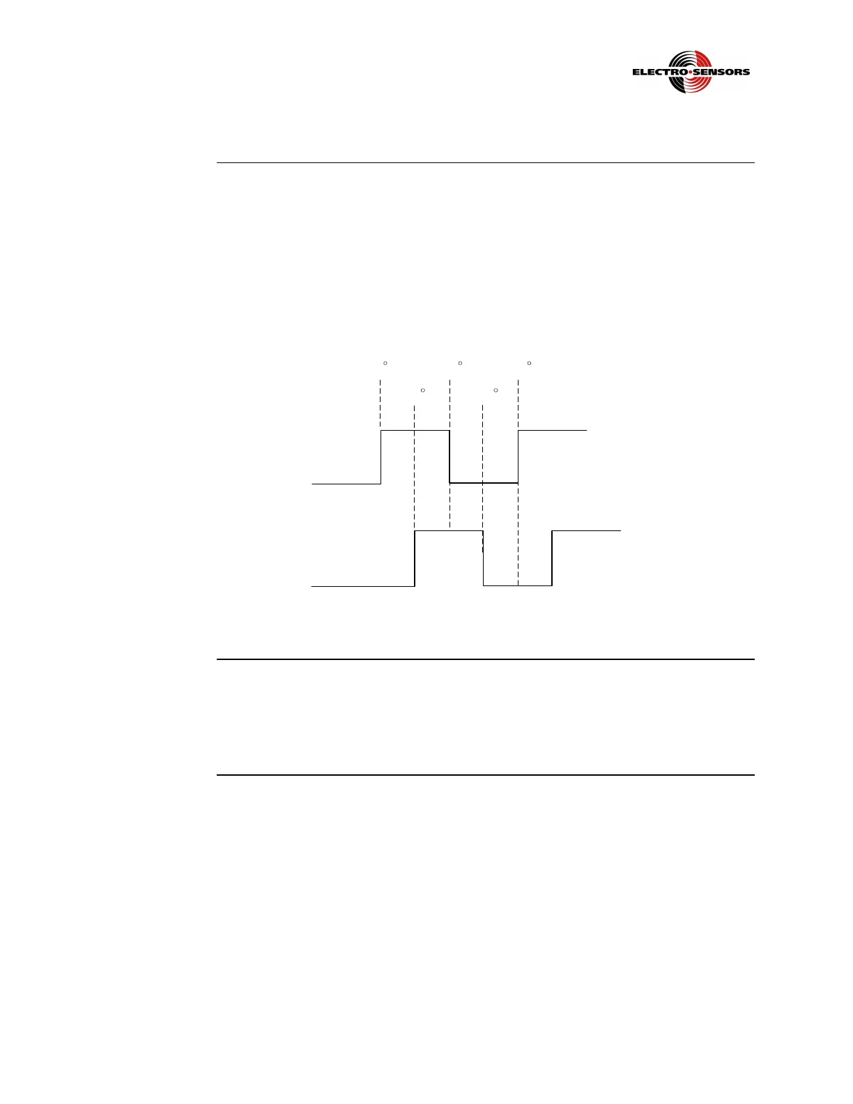
• Quadrature − Quadrature signals are configured for speed and direction. Sensor
wiring is across TB2, 7 and 8. Rate information is provided by a two-channel
quadrature pulse generator with a 90º phase shift between the signals, as shown
in Figure 6.
90
0
360180
270
Output (2)
Output (1)
Figure 6: Two-Channel Quadrature Signals 90º Phase Shift
A and B
channel input
signals
These inputs require a frequency input relative to speed. Devices such as Hall-Effect
sensors, encoders, or magnetic pickups can be used. Voltage to these sensors is from
TB2−6 (+12 Vdc) and TB2−5 (common). The maximum current draw available is
100 mA @ 12 Vdc, unregulated.
 Loading...