39
Rev G
S5−
−−
−TR400 Programming
Programming the switch inputs
Overview
The switch inputs are configured using variable 14. The switch inputs can be
configured to Reset the outputs or freeze the display.
For switch input wiring, see the TR400 Wiring & DIP Switches section.
When the digital input function is programmed as a Reset input and the switch input remains
closed, the relay will never turn OFF regardless of the operating condition. A momentary
contact closing of the switch is advised. Failure to observe this caution could result in damage
to the equipment.
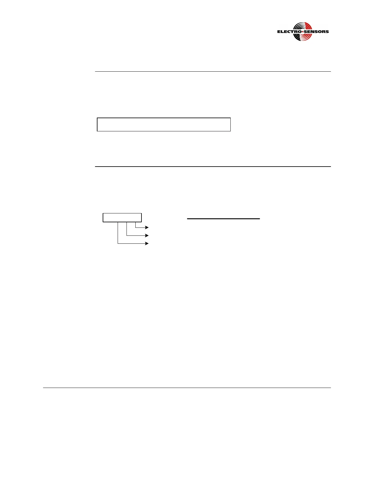
Variable 14,
switch input
function
selection
This variable configures the function of the switch inputs.
The input functions’ bit assignments are as shown below:
Digital Input Functions
0 = Unused
1 = Reset Output 1
2 = Reset Output 2
3 = Reset Output 3
4 = Reset Output 4
5 = Reset Output 5
6 = Reset Output 6
7 = Reset Outputs 1-6
8 = Display Hold
9 = System Reset
Input 1
00 0 0
Input 2
Input 3
Reset Output Deactivates the latch and energizes the output. Upon switch release
the relay will switch based on logic.
Display Hold Freezes the display. The analog output and set points are unaffected
by this switch.
System Reset All set points are reset and energized until the switch is released
and the start-delay timer times out. This allows the monitored shaft
to reach proper operating speed and eliminates the need for an
external start-delay relay.
 Loading...