16
Rev G
S3−
−−
−
TR400 Wiring & DIP Switches
A and B channel input signal wiring
Never use shielded cable
U
with extra conductors
U
. Extra conductors can act as antennas, picking
up electrical noise. Failure to observe this caution could result in improper sensor operation.
A and B
channel input
signal wiring
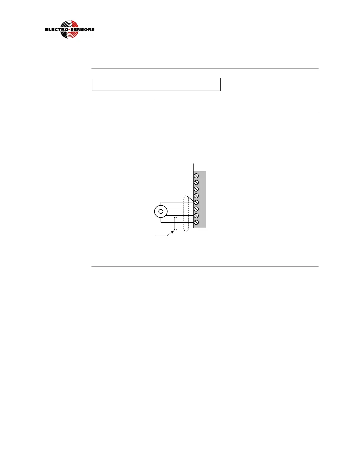
Wiring to these inputs should be shielded cable, with the shield tied to TB2−5
common only. TB2−7 is the single-channel A input signal, and TB2−8 is the channel
B input signal. TB2−8 is Quadrature only. See Figure 7.
Figure 7: Wiring for Channels A and B Input Signals
TB2
1
2
3
4
5
6
7
8
NC
Common
Signal A
Signal B
Quad Only
+12 V Supply
 Loading...