14
Rev G
S3−
−−
−
TR400 Wiring & DIP Switches
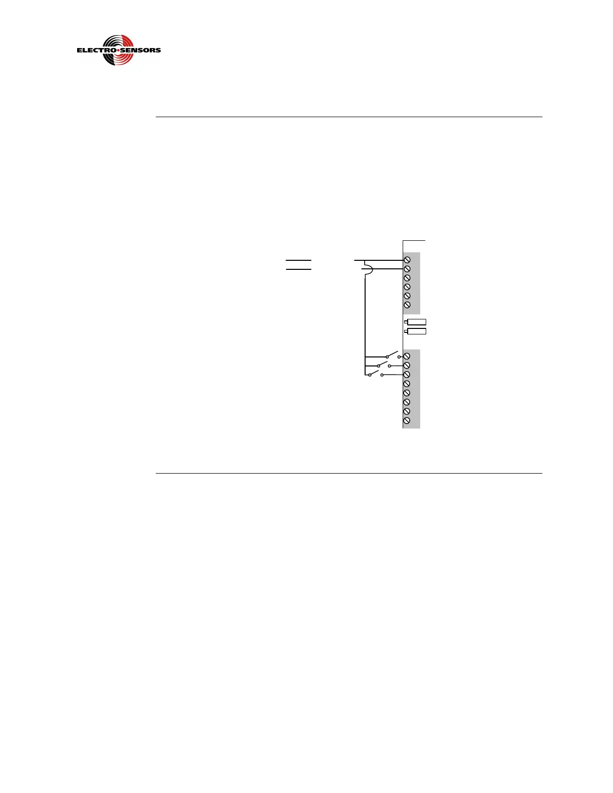
Switch input wiring
Switch inputs
and wiring
There are three (3) switch inputs that are programmable using variable 14. They are
used to Reset the outputs, or to freeze the display. Inputs 1, 2, and 3 require a voltage
equal to the supply voltage, which is at the same potential as the input Line (L1)
voltage. The opposite sides (non accessible) of these solid-state inputs are tied to
input Neutral (L2). Wire input 1 to TB2−1, input 2 to TB2−2, and input 3, to TB2−3.
See Figure 5.
TB1
1
2
3
4
5
6
TB2
1
2
3
4
5
6
7
8
DC Power AC Power
(+) Line (L1)
(-) Neutral (L2)
Switch Inputs
Figure 5: Wiring for Switch Inputs
 Loading...