44
Rev G
S6−
−−
−TR400 Diagnostics
Switch input test
Overview
The Switch Input diagnostic tests the TR400’s ability to recognize switch inputs tied
to TB−1. When a closed switch is tied to TB−2, screw tap 1, 2, or 3, the
corresponding bit position will toggle to “1.”
Switch input
test
To test the switch inputs, do the following:
Step Action
1.
Press the DIAG key.
2.
Press the UP ARROW key and the display will show the status of the
three (3) switch inputs.
When a switch is activated at one of the inputs, the corresponding display
character toggles to “1.” When an input turns OFF, the corresponding
display character toggles to “0.”
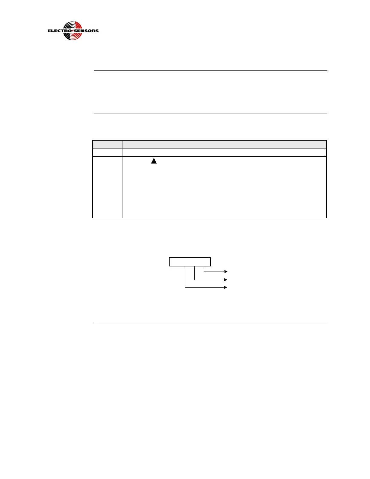
Figure 17 shows the bit positions associated with the three (3) switch
inputs.
Input 1
Input 2
00 0 0
0 = OFF
1 = ON
Display Characters
Input 3
Figure 17: Display Bit Positions Associated with Switch Inputs
 Loading...