11
Rev G
S3−
−−
−TR400 Wiring & DIP Switches
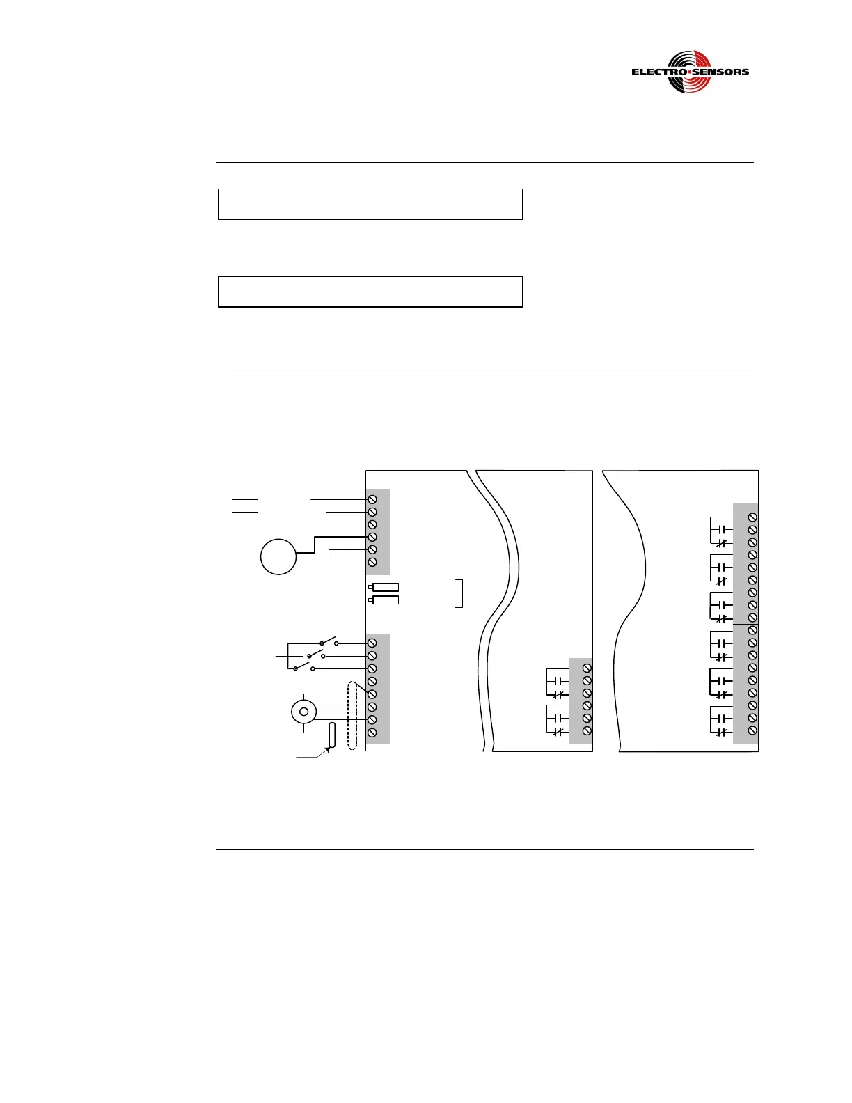
TR400 wiring schematics
Only qualified personnel should attempt to connect any wires to the TR400. Failure to observe
this warning could result in an injury to persons.
Do not wire the TR400 to 230 Vac or 10-30 Vdc unless it has been specially wired for that
voltage. The standard voltage setting is 115 Vac. Failure to observe this caution could result in
damage to the TR400.
Wiring
schematic
Figure 2 shows the various wiring schemes for the TR400.
TB1
1
2
3
4
5
6
(+)
(-)
(+) Line(L1)
(-) Neutral(L2)
Line
(same potential
as TB1-1)
1
2
3
4
5
6
TB3
TB2
1
2
3
4
5
6
7
8
NC
Common
+12 V Supply
Signal A
Signal B
Quad Only
Relay
Output 2
Relay
Output 1
Offset Pot
Span Pot
4-20 mA
PLC
NC
DC power AC Power
TB3
1
2
3
4
5
6
7
8
9
10
11
12
13
14
15
16
17
18
Relay
Output 1
Relay
Output 2
Relay
Output 3
Relay
Output 4
Relay
Output 5
Relay
Output 6
2 Relay option 6 Relay optionMain board
Figure 2: TR400 Wiring
Continued on next page
 Loading...