21
Rev G
S4−
−−
−TR400 Set-Up Parameters
TR400 parts and functions, continued
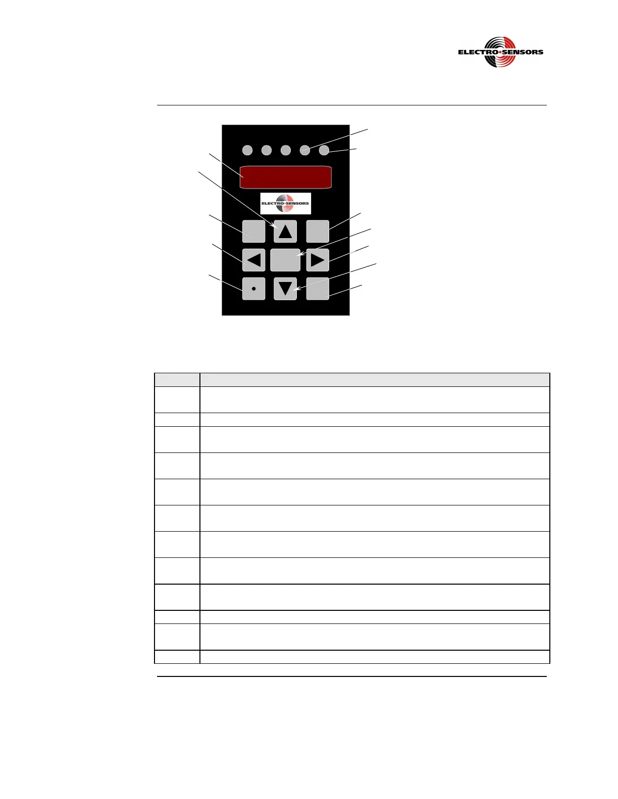
Figure 9b: TR400 Front Panel Description
Table 3: TR400 Panel Parts and Functions (continued)
Part Function
D The OUT 2 LED will light when relay “2” is activated. Relay “2” is enabled
by variable 13, and its set point value is entered in variable 10.
E The KEY ERR LED will light when the wrong key is pressed.
F The REV key is used to establish reverse direction when programming
variables 15 and 16.
G The ENTER key is used in Program Mode to set the value of a variable after
it has been changed.
H The RIGHT ARROW key, when pressed, selects the next digit to the right
when in Program Mode.
I The DIAG key, when pressed, enters Diagnostic Mode. Press the DIAG key
again to exit Diagnostic Mode.
J The DOWN ARROW key, when pressed in Program Mode, decrements the
active digit position on the display down by one (1).
K The DECIMAL POINT key, when pressed when in Program Mode, moves
the decimal point to the left one place.
L The LEFT ARROW key, when pressed in Program Mode, selects the next
digit to the left.
M The VAR key when pressed, enters Program Mode.
N The UP ARROW key, when pressed in Program Mode, increments the
active digit position on the display up by one (1).
O Four-digit display.
TR400 RATEMETER
0 0 0 0
REV PROG
OUT
1
KEY
ERR
OUT
2
REV
DIAG
VAR
ENTER
E
F
G
H
I
D
 Loading...