SOI/DT 2003 -01 eb 34 599 35 63-72
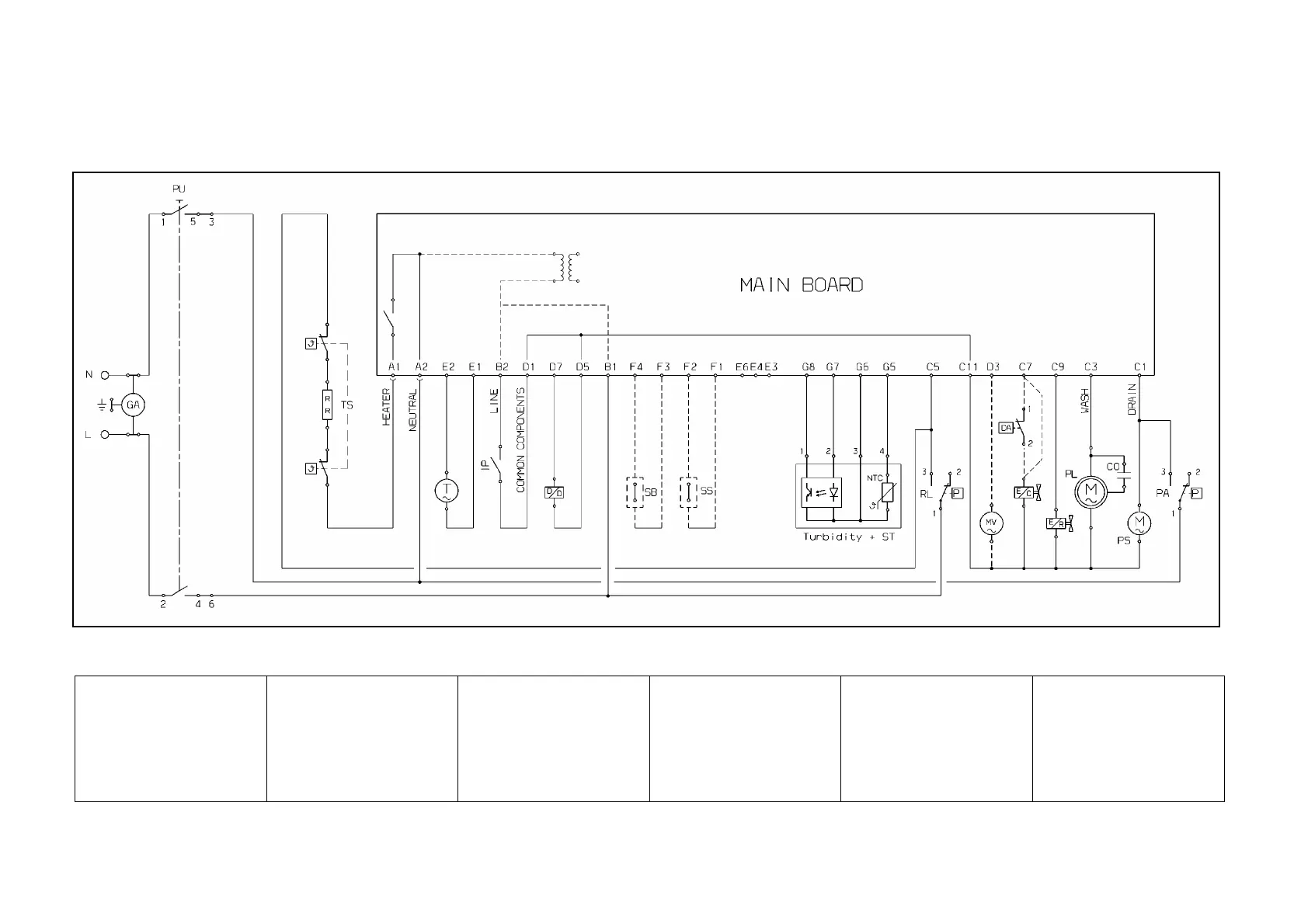
11.2 Basic circuit diagram
11.2.1 Key to circuit diagram
AR = Orange
BI = White
BL = Blue
CE = Light blue
GI-VE = Yellow-Green
MA = Brown
NE = Black
RO = Pink
VI = Lilac
AA/DA = Anti-flooding device
Beamer = Beamer
CO = Capacitor
DD = Detergent/ Rinse-aid
dispenser
EC = Fill solenoid
ER = Regeneration solenoid
GA = Suppressor
IP = Door switch
MR = General terminal block
MV = Fan motor
PL = Washing pump
PS = Drain pump
PU = Pushbutton array
PR/RL = Level pressure switch
PA = Anti-overflow pressure
switch
RR = Heating element
SB = Rinse-aid sensor
SS = Salt sensor
Turbidity = Turbidity sensor
ST = Temperature sensor
TAC/T = Tachymetric generator
TS = Safety thermostat
Main Board = Main board
User Interface = Display board