SOI/DT 2003 -01 eb 36 599 35 63-72
11.4 Checking the efficiency of the components
In order to facilitate the control procedure for the components to be tested, a TEST PROCEDURE has been
created which indicates the point to which the probes of the tester should be applied and the correct
theoretical value for each component tested.
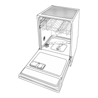
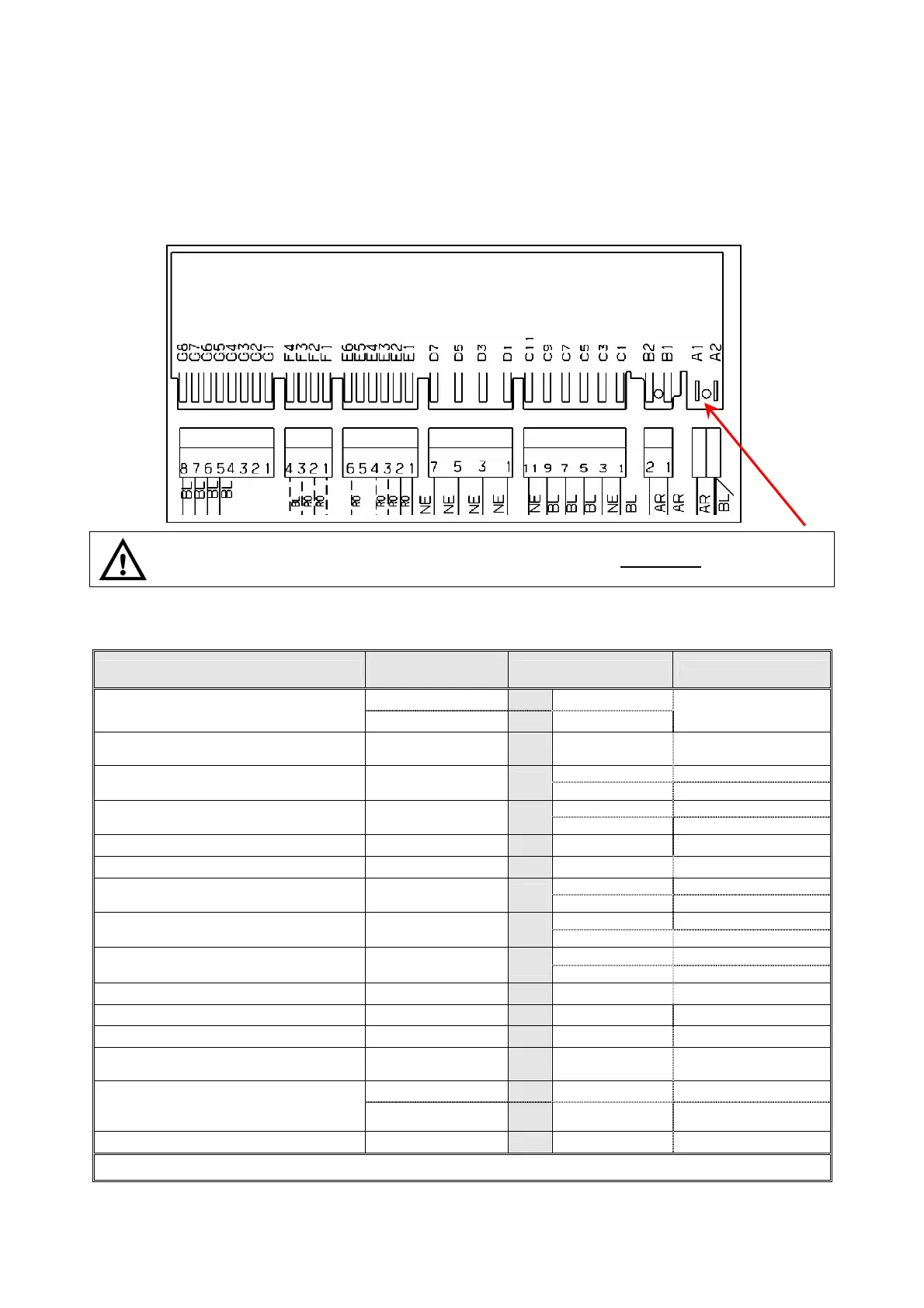
Remove the door and detach all the connectors from the main board.
Connect the probes of the tester to the appropriate points on the connector. Compare the ohmic reading
with the theoretical value.
Care should be taken relative to the position of connector "A1" - "A2": if this connector is
replaced in the incorrect position (back-to-front), the appliance will not function. The board will
not accept any commands since the power supply will be disconnected.
11.5 Measurement points on the board wiring connector
LIST OF COMPONENTS
PROBE
CONTACTS
CORRECT VALUES NOTES
L
B1
0 Ω
ΩΩ
Ω
* POWER CABLE &
(PU) - ON/OFF SWITCH
N
A2
0 Ω
ΩΩ
Ω
with ON/OFF key
pressed
(RR) - HEATING ELEMENT +
(TS) - SAFETY THERMOSTAT
A1
C5
25 Ω
Ω Ω
Ω ±
8%
connected in series
(2100W)
INFINITE
on "EMPTY" (1-2)
(PR) - LEVEL PRESSURE SWITCH
B1
C5
0 Ω
ΩΩ
Ω
on "FULL" (1-3)
INFINITE
on "EMPTY" (1-2)
(PA) - ANTI-FLOODING PRESSURE
SWITCH
C1
A2
0 Ω
ΩΩ
Ω
on "FULL" (1-3)
(IP) - DOOR MICROSWITCH
B2
D1
0 Ω
ΩΩ
Ω
Door closed
(DD/DB) - INTEGRATED DISPENSER
D5
D7
1.500 Ω
Ω Ω
Ω ± 8%
OK
INFINITE
with Rinse-aid
(SB) - RINSE-AID SENSOR
F3
F4
0 Ω
ΩΩ
Ω
without Rinse-aid
INFINITE
with salt
(SS) - SALT SENSOR
F1
F2
0 Ω
ΩΩ
Ω
without salt
4850 Ω
Ω Ω
Ω ± 5%
(at 25ºC)
(ST) - TEMPERATURE SENSOR
G5
G6
1205 Ω
Ω Ω
Ω ± 5%
(at 60ºC)
(GT) - TACHYMETRIC SENSOR
E1
E2
210 Ω
Ω Ω
Ω ± 8%
OK
(MV) - FAN MOTOR
D1
D3
7750 Ω
Ω Ω
Ω ± 8%
OK
(ER) - REGENERATION SOLENOID
D1
C9
6 KΩ
Ω Ω
Ω ± 8%
OK
(EC) - FILL SOLENOID +
(AA) - ANTI-FLOODING DEVICE
D1
C7
3.800 Ω
Ω Ω
Ω ± 8%
connected in series
C11
C3
50 Ω
Ω Ω
Ω ± 8%
start-up winding
(PL) - WASH MOTOR
To the two motor
wires (blue) / (red)
180 Ω
Ω Ω
Ω ± 8%
auxiliary winding
(PS) - DRAIN MOTOR
C11
C1
180 Ω
Ω Ω
Ω ± 8%
OK
Note: - *) = Measurement points L and N refer to the pins of the plug fitted to the power cable.