be taught with the TCP as the reference point. The tool dimensions are automatically calculated on
the basis of these seven points.
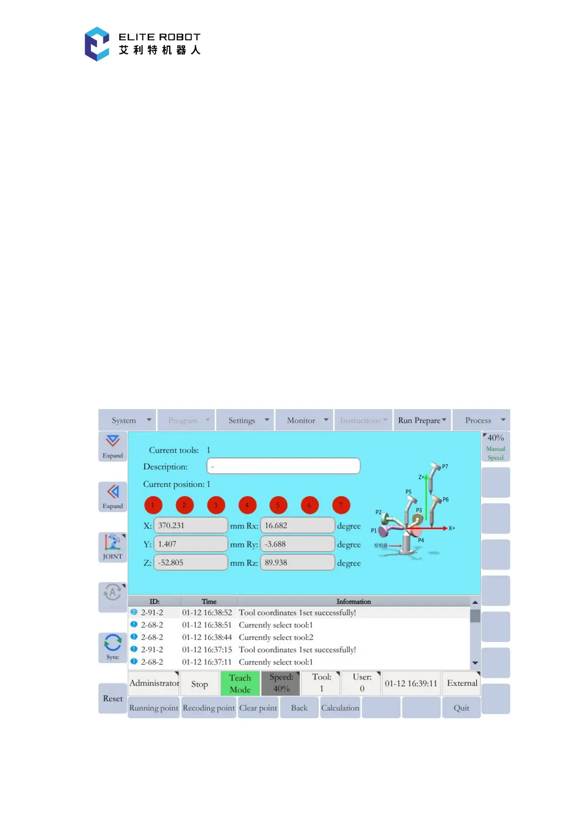
In the page of tool coordinates, press [CALIBRATE] in the submenu area to enter the
seven-point tool calibration window. Then record seven points numbered from P1 to P7 according
to the schematic diagram. For the five points from P1 to P5, the TCP should always be the same
point (e.g., the tip of the calibration cone), and each angle must be arbitrary. Accuracy may
decrease when pose setting is rotated in a constant direction. The points P6 and P7 are used to
define the X-axis direction and the Z-axis direction of the tool coordinate.
First select the target point in the window, then press [RECORD] to record the current
position of the manipulator. After that, the color corresponding to the point will change from red
to green. Record the seven points respectively. After selecting the taught point, [RUN POINT]
button can be pressed to move the manipulator to the point, and [CLEAR POINT] button can be
used to clear the point data. After teaching all points, press [CALCULATE] to generate the desired
tool coordinate.