Adjustment of the generators
98
SM/Transsonic_LC/1104/D © Elma GmbH & Co KG
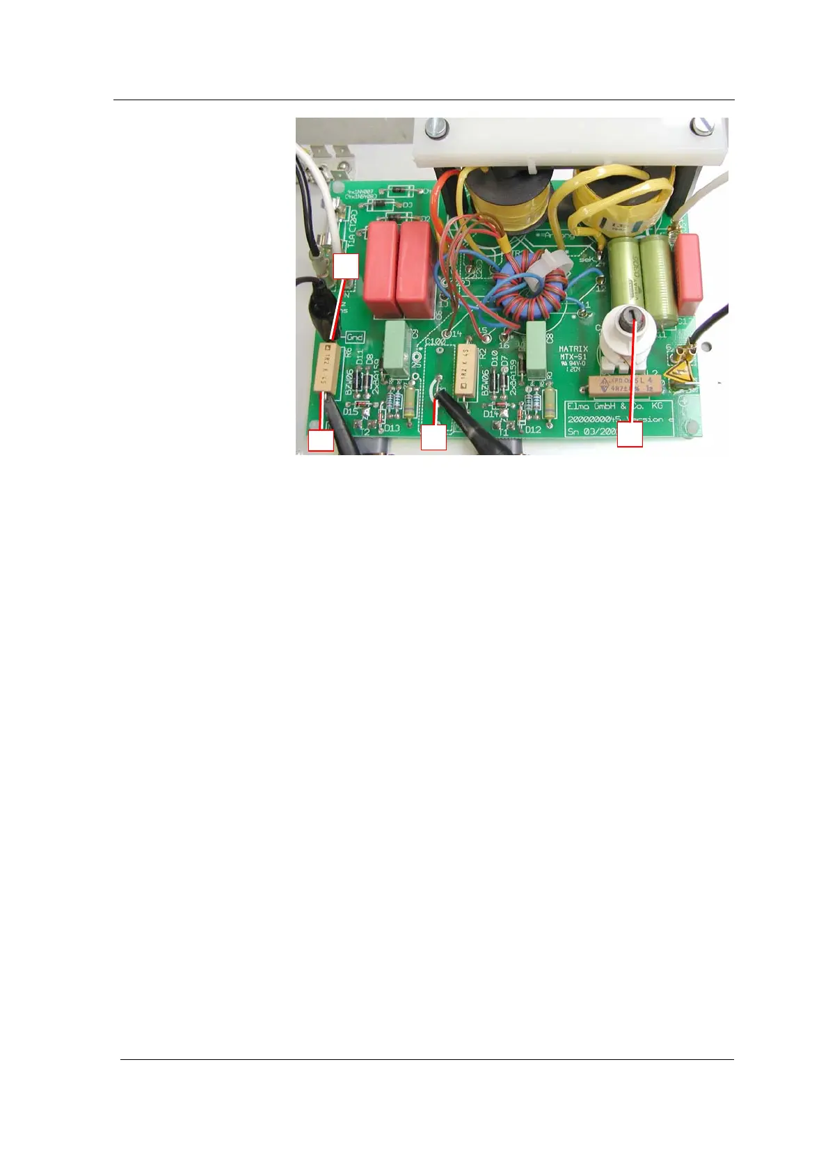
Illustration 16.6.1. Generator print: relevant adjustment points
Probe channel 1 – measurement of collector signal (connection
of probe at soldering fix point / or bridge MP1).
Probe channel 2 – measurement of emitter signal (connection
of probe at resistance R6 – on transistor side MP2).
Mass connection of probe channel 2 (resistance R6 – Gnd).
Adjustment coil to carry out adjustment: turn ferrite core in or
out (according to instructions).
A
B
D
C
B
C
D