Adjustment of the generators
86
SM/Transsonic_LC/1104/D © Elma GmbH & Co KG
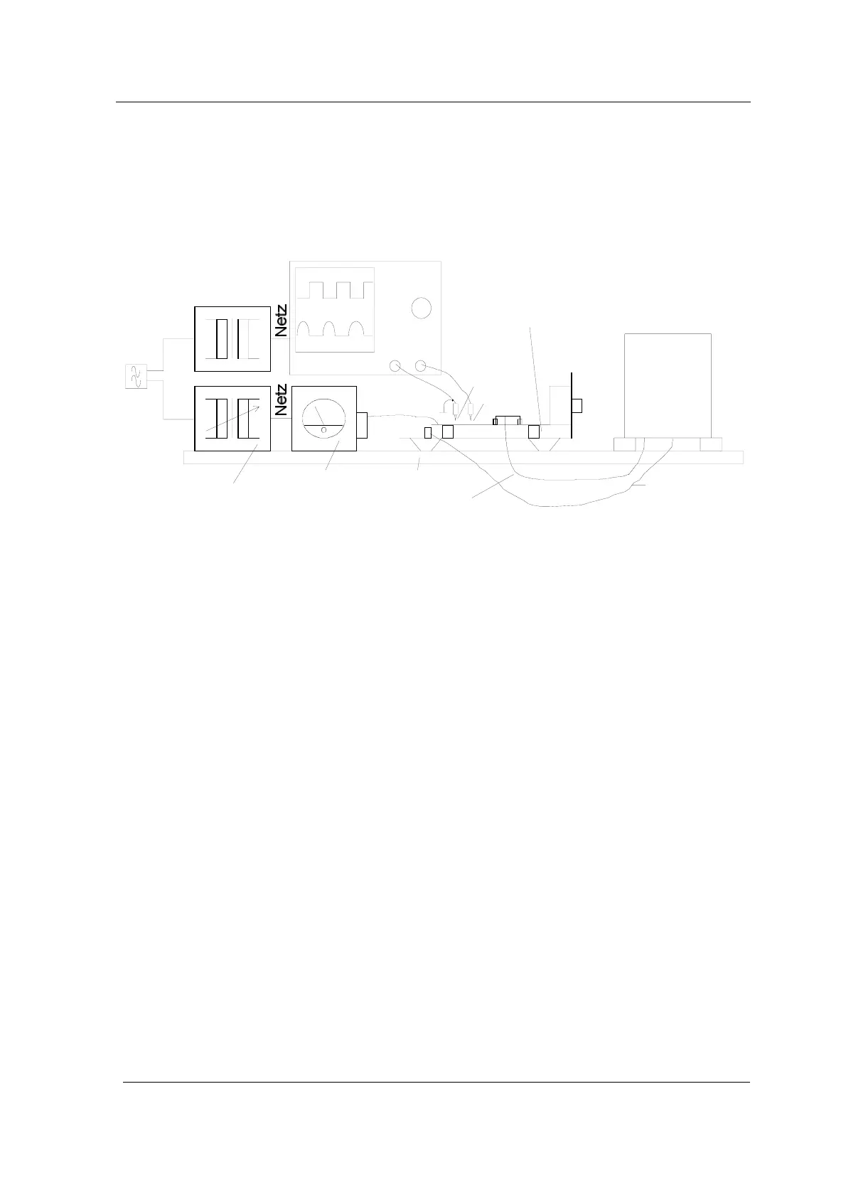
16.1 Set-up of measuring instruments
In order to carry out the generator adjustment, the graphs of the
voltage and the current at the transistor must be indicated
parallel by the oscilloscope. Set the instruments up as follows.
Regelbarer
Trenntransformator
Wattmeter
Arbeitsplatte
Erdleitung
Zuleitung Schwingsysteme
gefüllte Wanne
Bodenplatte
mit Generator
2-Kanal-Oszilloskop
Trenn-
transformator
CH1
CH1
CH2
CH2
MP1
MP2
Netz
Netz
Bild 8
Datei:c:\daten\texte\techdok\...\BILD008.DRW
Gnd
Illustration 16.1.1. Schematic set-up of measuring instruments
• CH (channel) 1 for the measurement of the voltage signal
(clock signal at transistor base):
voltage 10V / DIV (if a probe 1:10 is used)
• CH (channel) 2 for the measurement of the current graph
(emitter output signal):
voltage 0.1 V / DIV (if a probe 1:1 is used)
• TIME (basic): 5 µs
• Trigger CH1
• Trigger HF
16.2 Measuring process
Prepare the measuring set-up with connected transducer tank
and generator.
Fill the transducer tank approx. 2/3 with water and a little
cleaning medium.
(See also section 17. Initial operation and 17.2. Cleaning
media)
Connect the transducer system to the output of the generator
print before putting any voltage on the set-up.
Set values
oscilloscope
Preparation
Fill transducer tank
Connect the
transducer system