Adjustment of the generators
© Elma GmbH & Co KG SM/Transsonic_LC/1104/D
87
Slowly increase the voltage and observe the correct forming of
the graph at the oscilloscope. Also check the current
consumption in order to be able to reduce the voltage
immediately should a short circuit occur.
The adjustment process varies according to the type of unit.
Please follow the instructions given specifically for the individual
unit types on the following pages.
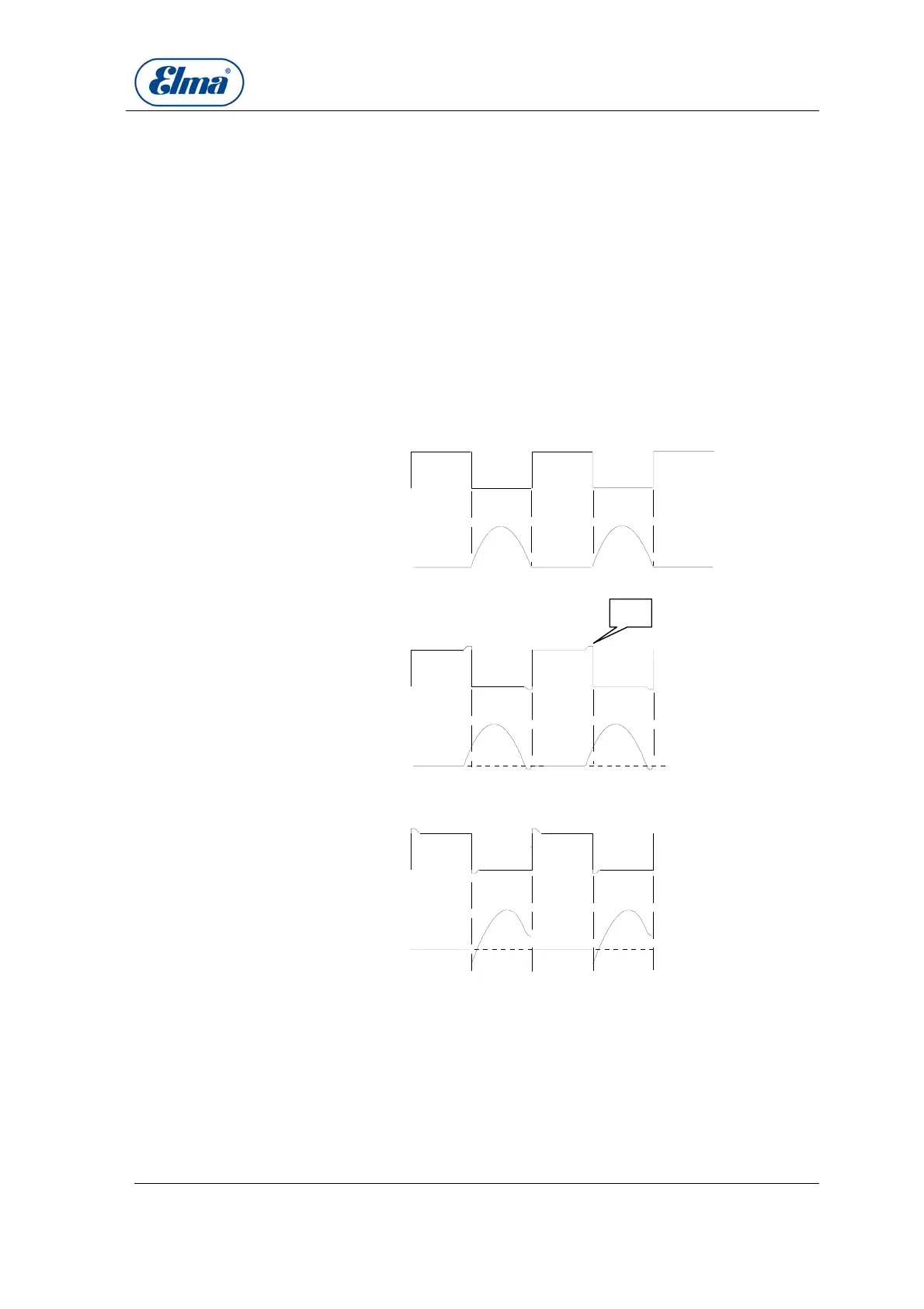
Measure the voltage and current graph at the measuring points
MP1 and MP2 according to the generator type (see section
15.4. – 15.7.)
The measured graphs must be exactly in phase
(see Illustration 16.2.1.). Exception: T780-T1060H.
MP1 (CH1)
MP2 (CH2)
T1
MP1 (CH1)
MP2 (CH2)
T1
Spannung
Strom
Spannung
Strom
MP1 (CH1)
MP2 (CH2)
T1
Spannung
Strom
Bild 13
13a
13b
13c
Peak
Datei:c:\daten\texte\techdok\...\BILD013.DRW
Illustrations 16.2.1. – 16.2.3.
If the graphs do not correspond, there is a high output loss in
the electronics. The transistors can be destroyed by thermic
overload.
The ultrasonic effect is unsatisfactory: there are no waves on
the surface of the bath, there are streamers on the tank floor,
there is an unusual noise, the transistors heat up, etc.
Slowly increase
voltage
General procedure
Illustration 16.2.1.
Peak
Illustration 16.2.2.
Ilustration 16.2.3.
Adjustment outside
tolerance