Faulty PXE transducer disks
48
SM/Transsonic_LC/1104/D © Elma GmbH & Co KG
4. Check each transducer disk for hair cracks and scorchings,
check the insulating sleeves for scorchings. Always change
the aluminum washers when you open the system.
For assembly of the transducer system ensure that all contact
surfaces are clean.
The transducer disk must be poled correctly. Observe the
markings on the PXE transducer disks, see Illustration 10.1.5.
How to assemble the
transducer system
1. Put a drop of Loctite or similar onto the thread of the
coupling piece (to lock the screw).
2. Assemble the individual parts of the transducer system
exactly as shown in the illustration.
3. Important! The black markings must point to the PLUS
terminal lug.
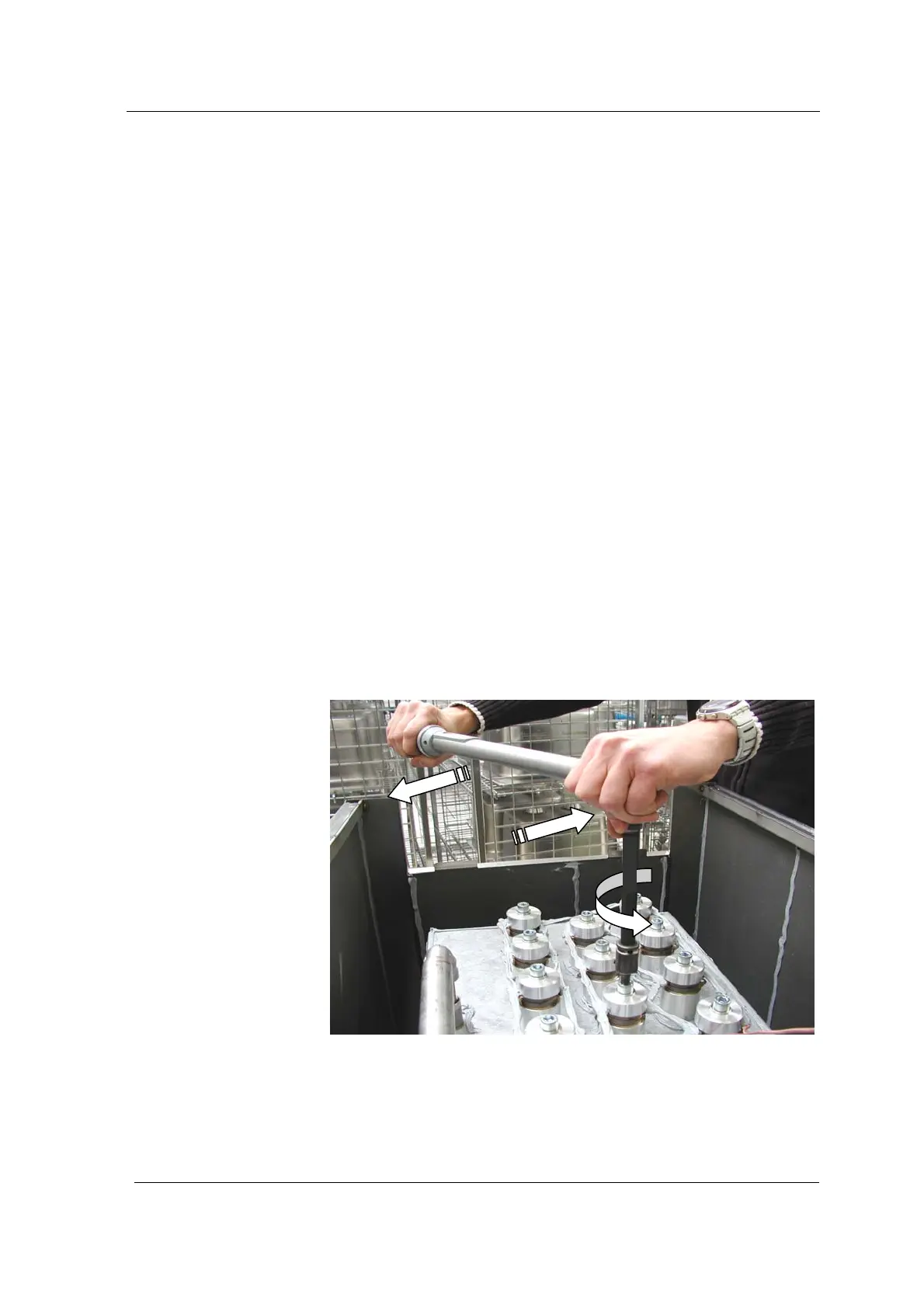
4. Screw in the transducer system screw and fix it with the
torque wrench.
Systems with 1 PXE disk at 46 Nm.
Systems with 1 PXE disk at 58 Nm.
Caution: The transducer disk is charged with electricity
when the transducer system screw is tightened. Branch off
the electric charge by short circuiting between two terminal
lugs, e.g. with a screw driver.
Illustration 10.1.1. Always hold the torque wrench vertically. Do not tilt
the tool!