Adjustment of the generators
© Elma GmbH & Co KG SM/Transsonic_LC/1104/D
91
Perfect adjustment
• The transistors do not heat up (one or both).
• There are waves on the surface of the bath.
• There are no streamers on the tank floor.
• The ultrasonic noise is uniform and not shrill.
• The performance changes only little when a beaker, etc. is
immersed in the tank.
The phases remain stable.
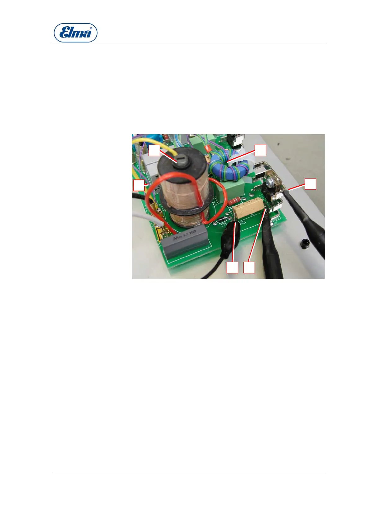
Illustration 16.4.1. Generator print: relevant points for the adjustment
Probe channel 1 – measuring of the collector signal (connection
of probe to cooling body).
Probe channel 2 – measuring of the emitter signal (connection
of probe at resistance R5 – on the transistor side).
Mass connection of probe channel 2 (resistance R5).
Control coil to carry out the adjustment. Adding or reducing of
coil wraps.
Cable for adjustment: Unsolder from fix point on generator print
and wrap or unwrap control coil.
Ferrite core of output transformer:
If output too high (compare Table 15.3.) slightly turn out ferrite
core anti-clockwise.
If output too low (compare Table 15.3.) slightly turn in ferrite
core clockwise.
Caution: The tip of the screw driver can heat up considerably
by induction.
F D
C B
A
E
B
C
D
E
F