Adjustment of the generators
© Elma GmbH & Co KG SM/Transsonic_LC/1104/D
95
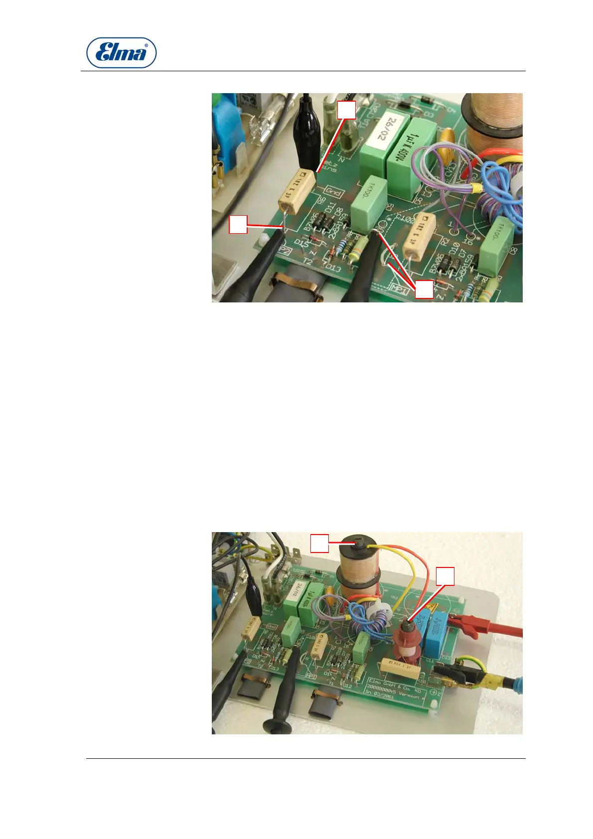
Illustration 16.5.1. Detail view connection probes
Probe channel 1 – measurement of collector signal (connection
probe at fix point / or bridge MP1).
Probe channel 2 – measurement of emitter signal (connection
probe at resistance R6 – on the transistor side MP2).
Mass connection of probe channel 2 (resistance R6 Gnd).
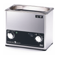
Adjustment coil for adjustment: turn ferrite core in or out
(according to adjustment instructions).
Ferrite core of output transformer:
If output too high (compare Table 14.3) slightly turn ferrite core
out counter-clockwise.
If output too low (compare Table 14.3) slightly turn ferrite core
in clockwise.
Caution: The tip of the screw driver can heat up considerably
due to induction.
Illustration 16.5.2. Generator print: relevant adjustment points
B
D
E
C
A
B
C
D
E