15
SETTING
UP
English
P
1~
P
32
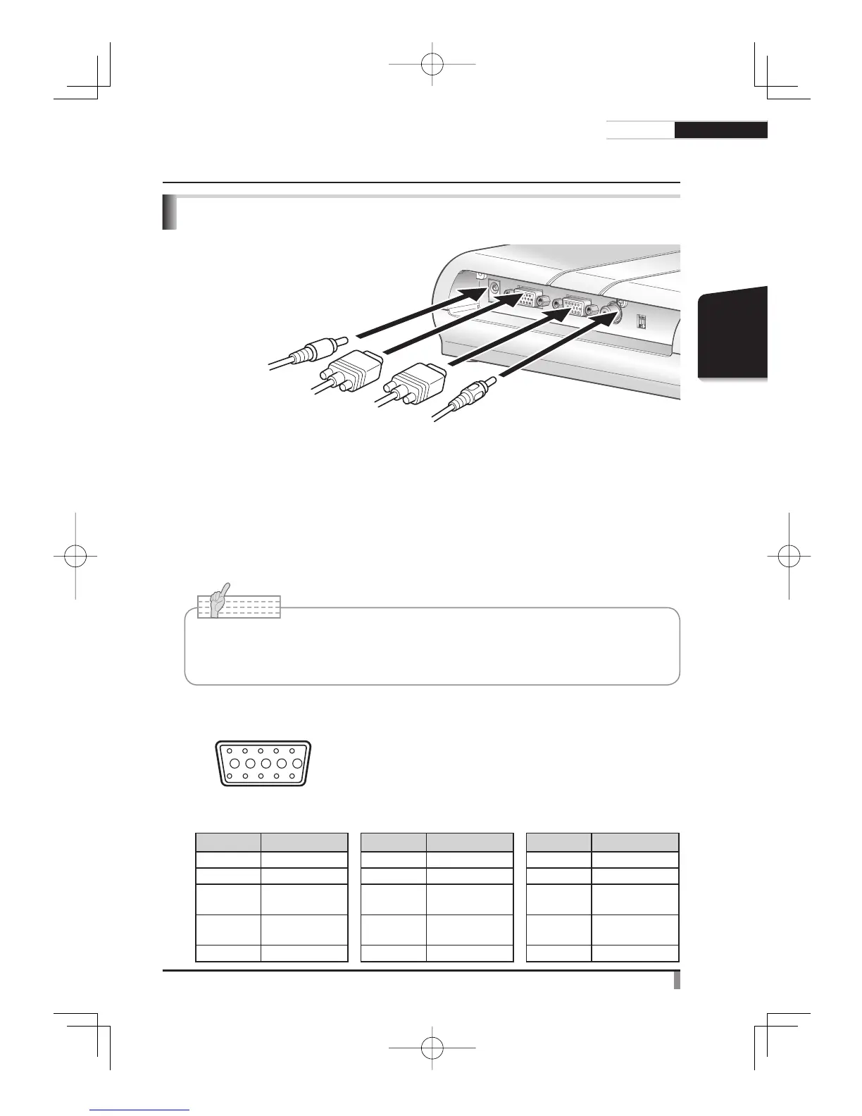
Connecting of AC adapter and Video cable
(1) Connecting to the unit with analog RGB input terminal equipped
Connect the supplied analog RGB cable to the [RGB OUT] terminal on the rear panel.
• The display position may be displaced from the center of the screen. In such case, adjust
the horizontal and vertical positions manually from the connected device.
• Vertical strips may appear on the projector or PC monitor screen. This can be mitigated
by manually adjusting the dot clock from the connected device.
(2) Connecting to the unit with analog RGB output terminal equipped
Connect the supplied analog RGB cable to the [RGB IN] terminal on the rear panel.
Specifications of the analog RGB input terminal of this product
Signal allocation
10
9876
54321
15 14 13
DSUB 15P shrink terminal (Female)
12 11
Video signal :
Horizontal synchronized signal :
Vertical synchronized signal :
Analog 0.7V(p-p) 75W terminated
TTL level (Positive/negative polarity)
TTL level (Positive/negative polarity)
Pin assignment
Pin No. Name Pin No. Name Pin No. Name
1
Video signal (Red)
6 GND (Red) 11 GND
2
Video signal (Green)
7 GND (Green) 12 N.C
3
Video signal (Blue)
8 GND (Blue) 13
Horizontal
synchronized signal
4 N.C 9 N.C 14
Vertical
synchronized signal
5 GND 10 GND 15 N.C
(3) VIDEO OUT terminal
• To TV monitor
(2) RGB IN terminal
• To PC
(1) RGB OUT terminal
• To projector
• To PC monitor
(4) DC IN 12V terminal
• To power plug
Note
• When using a notebook PC with an external output mode switching, set the notebook
PC side to the external output mode after pushing the manual operation button [PC] of
this equipment.