2002 by ELTRA GmbH Germany – January 2002 – Service Manual OH 900 / ON 900 / ONH 2000
2.5-3
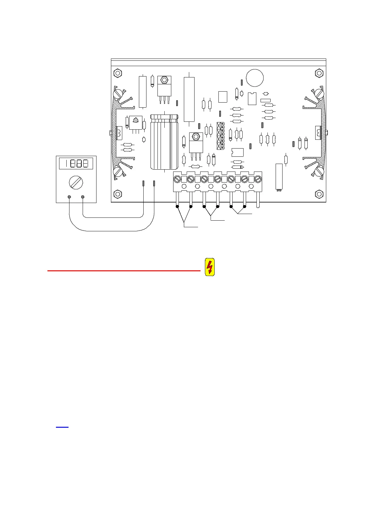
CAUTION! ELECTRICAL HAZARD !
You should be able to measure 200 V DC between TP 1 and TP 2 ( GND ) of the
NR32 board; otherwise the board is faulty.
This requires that 220 V AC comes through the connectors 6 and 7
If there is no 220 V AC, then there could be a bad contact in the plug.
The voltage for the infrared cell heating elements, comes from the connections 4 and
5 of the 7 pin plug, measure the voltage on the screws, without disconnecting the
plug.
As long as the LED is on, there is 200 V DC between 4 and 5.
As long as the LED is off, there is no voltage between 4 and 5.
If there is no voltage between 4 and 5, then the NR 32 is faulty. Replace it, according
to 3. 6.
■ The above sentences extend to the board TH61. From there they feed the heating
elements.
1
7 6 5 4 3 2
TP1 TP2
TP3
TP4
TP9
TP8
NR 32
15037
P1
TP5
+
TP7
VDC
COM
TP6
When the LED is on 200VDC
Supply voltage 220VAC
2-5-2
When the LED is on 12VDC
 Loading...


