2002 by ELTRA GmbH Germany – January 2002 – Service Manual OH 900 / ON 900 / ONH 2000
3.2-1
3.2
3.2
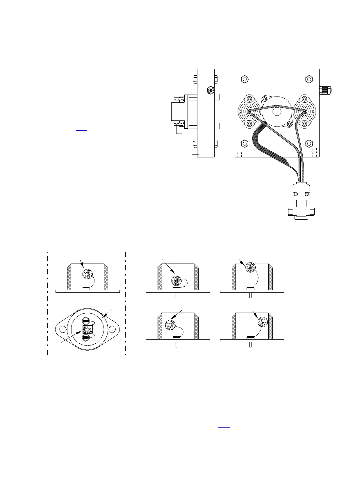
IR Source
The IR sources ( 2 ) are fastened
with the screws ( 3 )
For installing or removing the IR
source ( 2 ), the complete chopper
motor assembly ( 1 ) together with
the mounted paths and pre-amplifier,
should be removed from the infrared
unit, see 3. 5
In order to remove the IR source, it
suffices that the nuts ( 4 ) are
removed ( 5.5 mm wrench ).
In doing this, the screws ( 3 ) should
be held so that they do not turn with
the nuts.
The chopper motor housing ( 1 ) does
not need to be unscrewed.
The chopper motor housing ( 1 ) also
does not need to be unscrewed when
installing the IR sources ( 2 ).
CORRECT WRONG!
CAUTION !
The IR source ( 5 ) itself should be in the middle of the ring ( 6 )
( this is without considering the location of the soldered connections,
which are not centered ).
See above drawing: A and B are correct, C, D, E and F are wrong.
Avoid moving the IR source back and forth, try placing it correctly the first time.
After re-assembling the infrared cell, adjust according to 2. 3
C
D
E
F
5 5
5
5
B
A
5
6
5
3- 2-1
S
M 3
520
R -375
1
4
2
3
4 -1 -1