2002 by ELTRA GmbH Germany – January 2002 – Service Manual OH 900 / ON 900 / ONH 2000
3.11-3
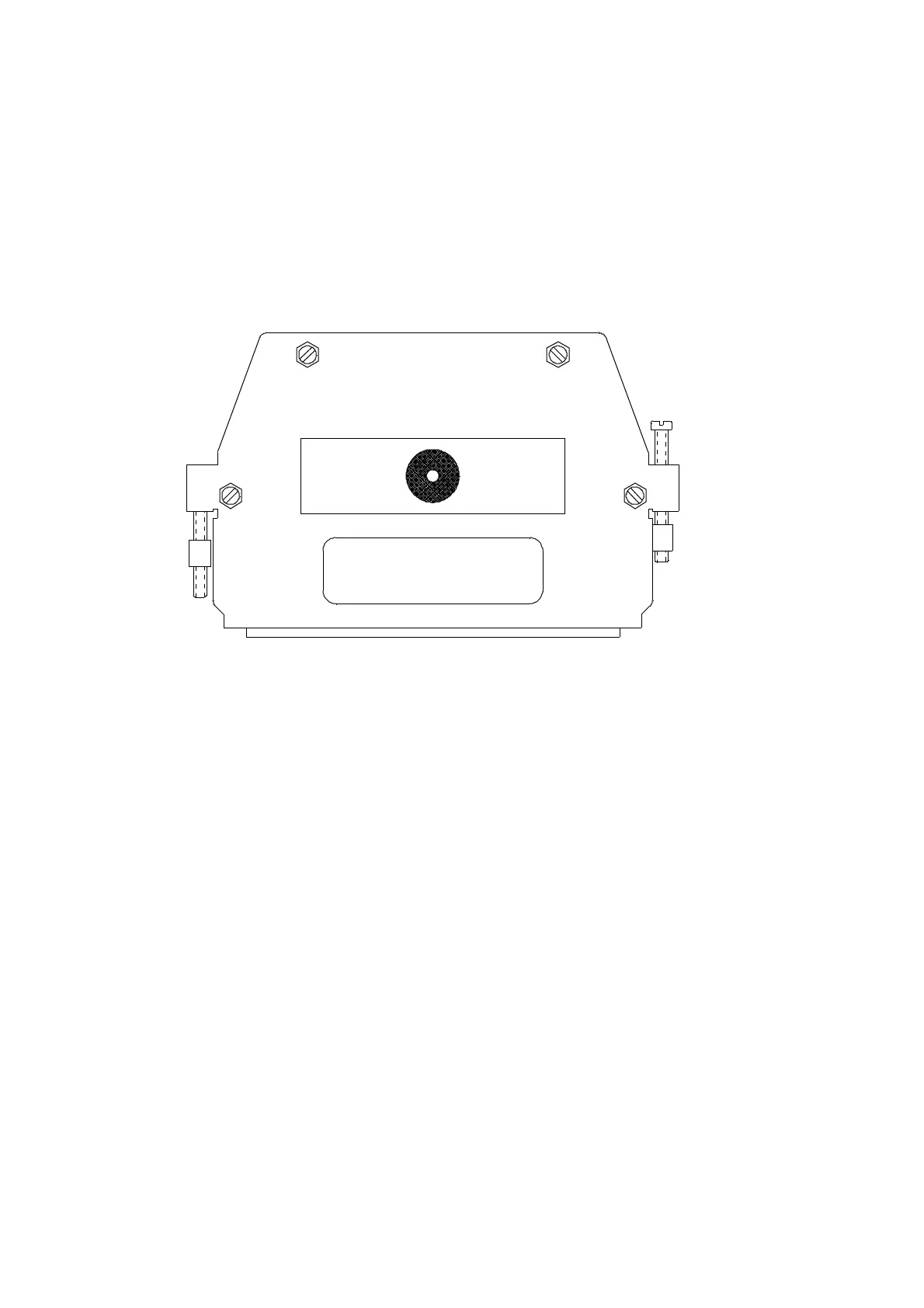
ONH-2000
The coding is done inside a 96-pin VG connector. The pins 27 through 32 are used for this
purpose.
For every channel combination, the pins at row A and row C are interconnected as
follows:
Labels on the connector, according to the instrument type.
Instrument Connections a with Code No.
version: c inside the connector: ( shown on display during
initialization )
1 x O 32,nc,30,29,28,nc 22
2 x N, 2 x H 32,31,nc,nc,28,nc 26
1 x O + 2 x N; 1 x O + 2 x H 32,nc,nc,nc,28,nc 2C
2 x O nc,nc,30,29,28,nc 23
2 x O + 2 x N; 2 x O + 2 x H nc,nc,nc,nc,28,nc 2F
Remark:
In case of 2 x H, 1 x O + 2 x H and 2 x O + 2 x H the ON / OH switch of the front panel
connects additionally 5c with 28a ( change from N to H ).
Caution :
The electronics unit takes notice of the new coding once the power is switched on.
3- 11
2xO+2xN
ONH2000
 Loading...


