EM TEST CNI 501 / CNI 503
Manual of operation V 3.32 22 / 41
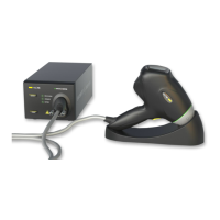
Surge coupling to CNV504 / 508 network for surge to signal- and data-lines
Connection of the surge coupling network for
data lines to CNI 503
HV: Coaxial cable
COM: Banana cable
PE: Use a separate cable for the Ground
connection
NOTE: The PE Earth should not connect to the PE output
on the front side of the CNI. This output is internal
separated over an additional inductance for decoupling.
Use the ground bolt on rear side or the reference ground.
Figure 6.8: Connection of a CNV 504 to a CNI 503
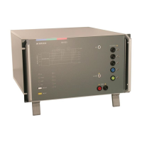
Burst coupling to HFK capacitive coupling clamp for signal- and data lines
Connection of the capacitive coupling clamp
HFK to CNI 503
Burst cable connections:
50 OHM - EFT: Coaxial cable
50 OHM -HFK: Coaxial cable
NOTE: The HFK should be placed on the reference ground.
The distance from the HFK to the EUT should be at least 0.5m.
The reason is the radiation of the coupling clamp.
Figure 6.9: Connection of a capacitive coupling clamp to the UCS 500 M4
 Loading...