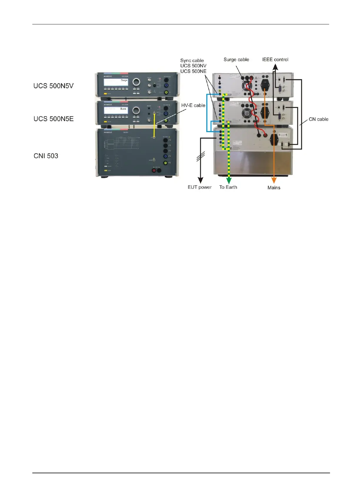
Arrangement
UCS500N5E next placed to the CNI 503. This allows the shortest possible cable for the EFT pulse from the
generator to the CNI 503.
UCS500NV located on top of the tower.
Front side cabling:
HV-E cable: UCS 500N5E EFT 50Ω output to CNI 503 EFT input
Rear side cabling:
Please take care to avoid current earth loops with the cable routing. If there are problems during the EFT / Surge
test, the cable layout may be the reason.
Earth connection:
- Earth to CNI 503
- CNI 503 to UCS 500N5E
- CNI 503 to UCS 500N5V
Surge HV cable:
- 2 HV cable cables twisted
CN control cable
Connect the Sub-D 15 pole CN-cable from the UCS 500Nx generator to the CNI 503
The CN plugs on CNI 503 are coded for the
- UCS 500N5V to CNI 503 UCS V left side
- UCS 500N5E to CNI 503 UCS E right side
IEEE control cable:
- UCS 500NE to common point
- UCS 500NV
 Loading...