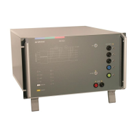
EM TEST CNI 501 / CNI 503
Manual of operation V 3.32 3 / 41
Contents
1. List of coupling networks ............................................................................................................................. 5
1.1. Coupling networks for IEC pulses ......................................................................................................... 5
1.2. Coupling networks as per IEC, ANSI and Ringwave ............................................................................ 6
1.3. Special Coupling networks .................................................................................................................... 7
2. Operating Functions ..................................................................................................................................... 8
2.1. Front view .............................................................................................................................................. 8
2.2. Rear side ............................................................................................................................................... 9
2.3. CNI 501 S1 .......................................................................................................................................... 10
3. General ......................................................................................................................................................... 11
3.1. Coupling modes .................................................................................................................................. 11
3.2. Coupling to Signal Lines ..................................................................................................................... 11
4. Technical Data CNI 503 ................................................................................................................................ 12
4.1. EUT power supply ............................................................................................................................... 12
4.2. DC current capability of CNI 503Nx .................................................................................................... 13
4.3. Technical data special CNI 503 .......................................................................................................... 14
4.4. General ................................................................................................................................................ 15
4.5. Test level with Burst as per IEC 61000-4-4 Ed.2. ............................................................................... 16
4.6. Decoupling inductors for surge pulse .................................................................................................. 16
5. Operation ...................................................................................................................................................... 17
5.1. Power supply input (EUT) ................................................................................................................... 17
5.2. Synchronization ................................................................................................................................... 17
5.3. Connection of DC Equipment.............................................................................................................. 18
5.4. Operation with CNI coupler or generator internal CDN ...................................................................... 19
6. Test set up .................................................................................................................................................... 20
6.1. Grounding ............................................................................................................................................ 21
6.2. Surge coupling to CNV504 / 508 network for surge to signal- and data-lines .................................... 22
6.2.1. Burst coupling to HFK capacitive coupling clamp for signal- and data lines ...................................... 22
6.3. Test setup CNI 503 with UCS500N5E and UCS500N5V generators ................................................. 23
6.4. Test setup CNI 501 / 503 with EFT 500/800 and VCS 500 generators .............................................. 24
6.5. test setup with CNI 501 BS3 or CNI 503B7.5 ..................................................................................... 25
7. ANSI Coupling (option) ............................................................................................................................... 26
8. CNI 503 Rack Mountain ............................................................................................................................... 27
9. Special coupling networks ......................................................................................................................... 28
9.1. CNI 501B9 ........................................................................................................................................... 28
9.1.1. Operating elements ............................................................................................................................. 28
9.1.2. Technical Data .................................................................................................................................... 29
9.1.3. AC Application ..................................................................................................................................... 29
9.1.4. DC Application..................................................................................................................................... 30
9.1.5. Schematics .......................................................................................................................................... 30
10. Maintenance and calibration ...................................................................................................................... 31
10.1. General ................................................................................................................................................ 31
10.2. Calibration and Verification ................................................................................................................. 31
10.2.1. Factory calibration .......................................................................................................................... 31
10.2.2. Guideline to determine the calibration period of EM Test instrumentation .................................... 31
10.2.3. Calibration of Accessories made by passive components only: .................................................... 31
10.2.4. Periodically In-house verification .................................................................................................... 31
11. Delivery Groups ........................................................................................................................................... 32
11.1. Basic equipment .................................................................................................................................. 32
11.2. Accessories and options ..................................................................................................................... 32

 Loading...