EM TEST CNI 501 / CNI 503
Manual of operation V 3.32 9 / 41
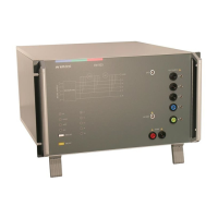
Figure 2.2: Rear side CNI 503 (4kV version)
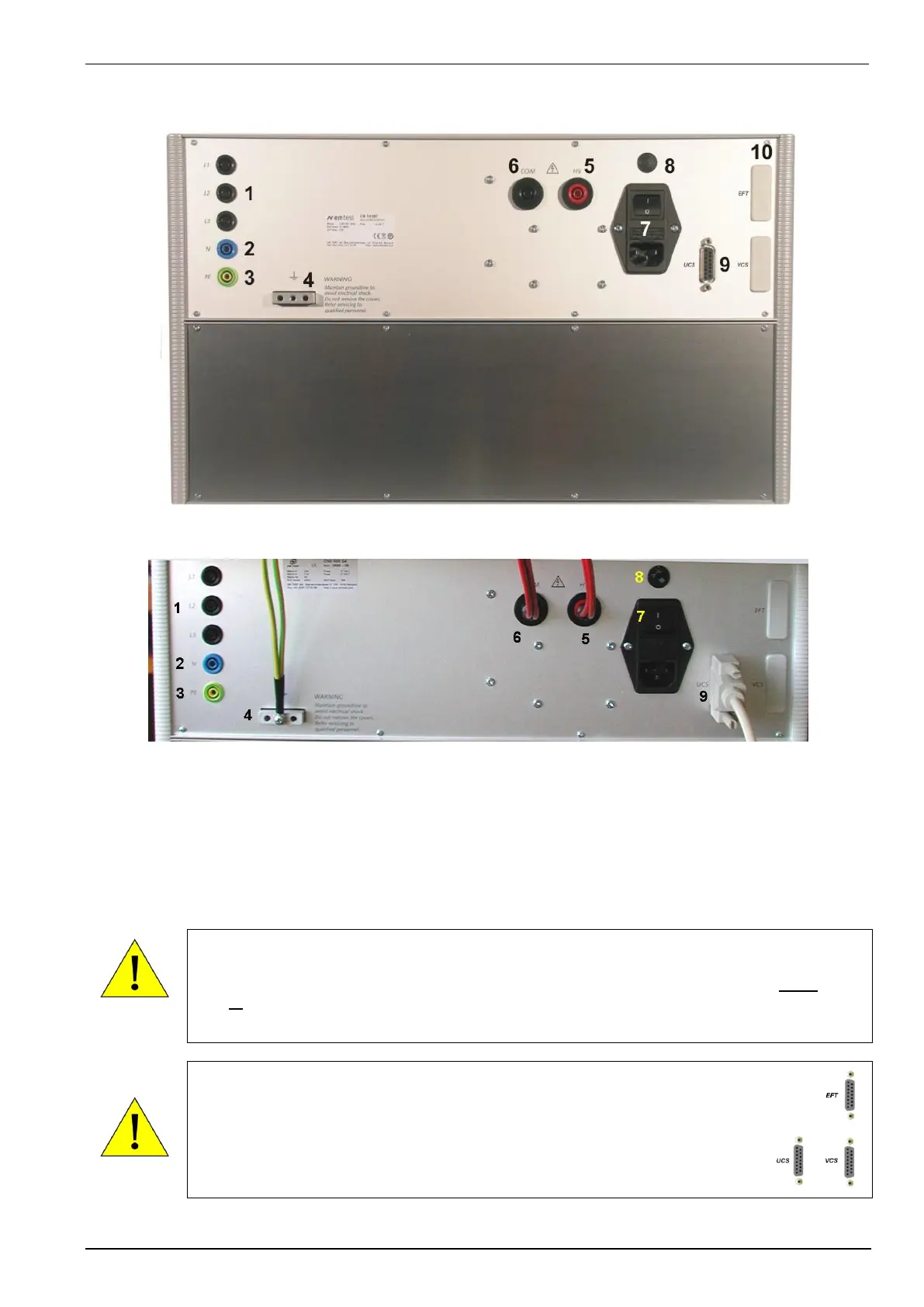
Figure 2.3: CNI 503 Rear side (> 4kV version)
1 EUT power L1, L2, L3
2 EUT power N
3 EUT power PE
4 Ground Reference
5 HV Input from generator
5 HV Input from generator
6 COM Input from generator
7 Power switch with fuse
8 Voltage selector 230V / 115V
9 CN control input from UCS generator
10 CN control input from EFT and or VCS generator
If the CNI 503 includes two or more CN interfaces for UCS500NE and UCS500NV, only one
generator is allowed to communicate to the CNI 503. In case that all remote control input, for UCS
(9) and EFT/VCS (10), are included in the CNI 503 the operator has to take care that either the
UCS or the EFT/VCS is controlling the CNI.
A simultaneous operation by more than one generators is not allowed.
The CN control input is available in two different versions.
- Interface to generators of the series UCS 500xx
- Interface to generators of the series EFT 500x and or VCS500x
The connectors have different pin configurations. Therefore each generator
must be plugged in as signed at the rear panel.
 Loading...