EM TEST VDS 200 Series
Manual for Operation V 5.19 14 / 57
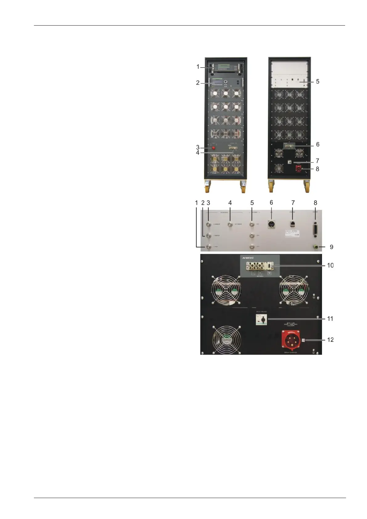
VDS 200N100.6 operating elements
General operating elements
1 Autowave (optional control device)
2 VDS200 front for manual operating
3 Emergency button (turn for release)
4 DUT supply ,sense front
5 Rear panel (VDS and Autowave functions)
6 DUT supply , sense rear side
7 Protection switch power supply
8 Mains input 4x400V 32A
Operating elements rear side
A Control
VDS 200N100.1
1 I Peak 1V = 50A
2 I Monitor 1V= 10A
3 U Monitor 1V= 10V
4 Ext Trigger
Autowave
5 Analog output channels 2, 3, 4
6 USB interface
7 Ethernet interface
8 GPIB IEEE 488 interface
B VDS 200N100 power part
9 Earth connection
10 DUT supply , sense rear side
11 Protection switch power supply
12 Mains input 4x400V 32A
The description of the Autowave interface and plugs refer to the Autowave manual.