116
RTC Timer (Apollolake) - User Guide
Appendix
IND100077-195
DOC207017- rev 01 – 2018-09-24 - Created by: 6644
Hatteland Display AS, Stokkastrandvegen 87B, N-5578 Nedre Vats, Norway
Tel: (+47) 4814 2200 - mail@hatteland-display.com - www.hatteland-display.com
User Guide RTC Timer - ApolloLake
All intellectual properties belongs to Hatteland Display AS
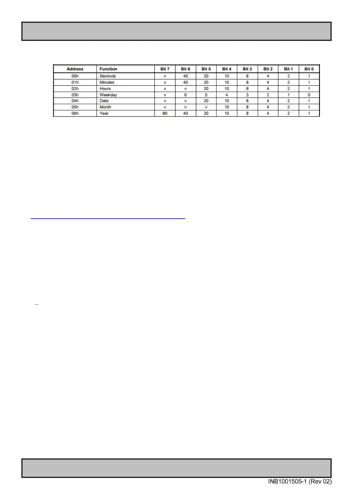
1. Time/Date Register definition in RTC timer
3 Driver support
3.1
Windows
Windows does not provide direct IO address access in user-space, so a third party driver/library is
required to implement the IO control logic in application.
Here we recommend a method of 3
rd
party driver: Inpout driver.
http://www.highrez.co.uk/downloads/inpout32/default.htm
“
The InpOut32 device driver supports writing to "old fashioned" hardware port addresses. It does NOT
support USB devices such as USB Parallel ports or even PCI parallel ports.
The device driver is installed at runtime. To do this however needs administrator privileges. On Vista
& later, using UAC, you can run the InstallDriver.exe in the \Win32 folder to install the driver
appropriate for your OS. Doing so will request elevation and ask for your permission (or for the
administrator password). Once the driver is installed for the first time, it can then be used by any user
*without* administrator privileges
“[1]
The inpout driver package consists of:
- Driver: Inpout.sys
- DLL file: Inpout.dll
Driver file is required to install beforehand. Then the user application call the provided interface to
read/write on IO port:
1. Set Output to IO port.
void Out32(short Address, short Data);
2. Read Input from IO address
short Inp32(short Address);
3. Check if InpOut driver is opened.
BOOL IsInpOutDriverOpen(void);
3.1.1 Example Code Windows
typedef void (__stdcall *lpOut32)(short, short);
DOC207017- rev 01 – 2018-09-24 - Created by: 6644
Hatteland Display AS, Stokkastrandvegen 87B, N-5578 Nedre Vats, Norway
Tel: (+47) 4814 2200 - mail@hatteland-display.com - www.hatteland-display.com
User Guide RTC Timer - ApolloLake
All intellectual properties belongs to Hatteland Display AS
(See note 1
Time/Date
Register
Definition)
Note:
1. Time/Date Register definition in RTC timer
2.1.3 Write Data to RTC timer
Set Slave Device
Register Address
0xXX
(See note 1
Time/Date
Register
Definition)
Set Slave Device
Register Data
0xXX
(See note 1
Time/Date
Register
Definition)
Note: